PARK ASSIST / MONITORING TELEVISION CAMERA(for Front) REMOVAL
CAUTION / NOTICE / HINT
The necessary procedures (adjustment, calibration, initialization or registration) that must be performed after parts are removed and installed, or replaced during front television camera assembly removal/installation are shown below.
| Replaced Part or Performed Procedures | Necessary Procedures | Effect/Inoperative Function when Necessary Procedures are not Performed | Link |
|---|---|---|---|
| Front television camera assembly (Including removal and installation) | Front television camera view adjustment | Panoramic view monitor system | ( 202304,999999,_56,_083082,_0586733,RM1000000029R9F,) 202304,999999,_56,_083082,_0586733,RM1000000029R9F,)
|
·
Front television camera assembly, radiator grille assembly or front bumper assembly ·
Rear television camera assembly ·
Side television camera assembly LH or outer rear view mirror assembly LH ·
Side television camera assembly RH or outer rear view mirror assembly RH |
Television camera view adjustment (Adjustment of all cameras)
|
| Replaced Part or Performed Procedures | Necessary Procedures | Effect/Inoperative Function when Necessary Procedures are not Performed | Link |
|---|---|---|---|
| Front television camera assembly (Including removal and installation) | Front television camera view adjustment | Panoramic view monitor system | (202304,999999,_56,_083082,_0586733,RM1000000029R9F,)
|
·
Front television camera assembly, radiator grille assembly or front bumper assembly ·
Rear television camera assembly ·
Side television camera assembly LH or outer rear view mirror assembly LH ·
Side television camera assembly RH or outer rear view mirror assembly RH |
Television camera view adjustment (Adjustment of all cameras)
|
PROCEDURE

 17751
1.REMOVE NO. 1 INLET AIR CLEANER (for Gasoline Model)
17751
1.REMOVE NO. 1 INLET AIR CLEANER (for Gasoline Model)
53510
2.REMOVE HOOD LOCK ASSEMBLY
16681A
3.REMOVE RADIATOR UPPER AIR GUIDE PLATE
Remove the 4 bolts.
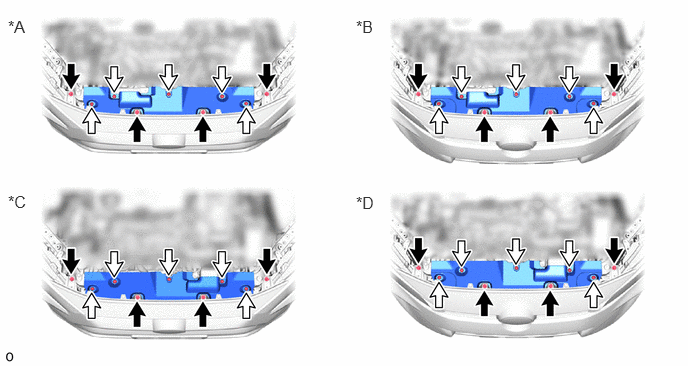
| *A | for Type A, Gasoline Model | *B | for Type B, Gasoline Model |
| *C | for Type A, HV Model | *D | for Type B, HV Model |

|
Bolt | 
|
Clip |
Remove the 5 clips.
Place your hands at the position shown in the illustration and lift up the front bumper cover to the point where the radiator upper air guide plate can be removed.
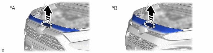
| *A | for Type A | *B | for Type B |

|
Place Hands Here | 
|
Pull in this Direction |
Pull in the removal direction and remove the radiator upper air guide plate.
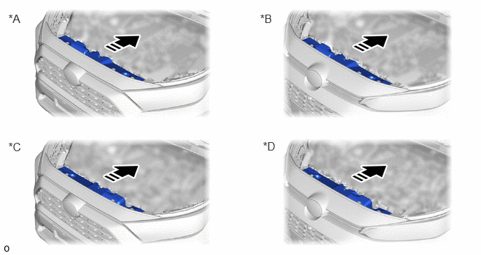
| *A | for Type A, Gasoline Model | *B | for Type B, Gasoline Model |
| *C | for Type A, HV Model | *D | for Type B, HV Model |
|
|
Remove in this Direction | - | - |
86790B
4.REMOVE FRONT TELEVISION CAMERA ASSEMBLY
Disconnect the connector.
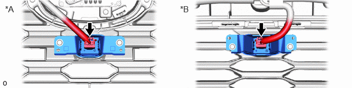
| *A | for Type A | *B | for Type B |
Remove the 2 screws.
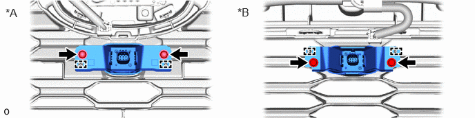
| *A | for Type A | *B | for Type B |
Detach the guide and remove the front television camera assembly.