INTERIOR PANELS / TRIM ROOF HEADLINING INSTALLATION
CAUTION / NOTICE / HINT
- HINT:
- ·
A bolt without a torque specification is shown in the standard bolt chart.
PROCEDURE

 65351A
1.INSTALL BATTERY HOLE COVER (for HV Model)
65351A
1.INSTALL BATTERY HOLE COVER (for HV Model)
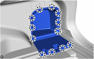
Attach the claw to install the battery hole cover.
64230A
2.INSTALL ROOM PARTITION NET ASSEMBLY
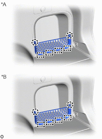
| *A | for HV Model |
| *B | for Gasoline Model |
Attach the guide and claw to install the room partition net assembly.
66425B
3.INSTALL REAR NO. 2 SIDE RAIL SPACER LH
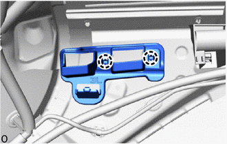
Attach the claw to install the rear No. 2 side rail spacer LH.
66415B
4.INSTALL REAR NO. 2 SIDE RAIL SPACER RH
- HINT:
-
Use the same procedure described for the LH side.
5.INSTALL ROOF HEADLINING ASSEMBLY (for Normal Roof)
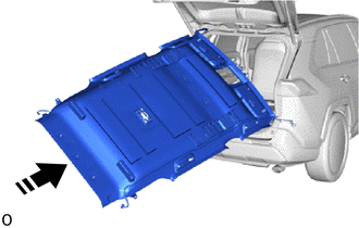

|
Install in this Direction |
Insert the roof headlining assembly into the cabin from the back door.
- NOTICE:
- ·
Installation of the roof headlining assembly must be performed by multiple people to prevent deformation of the roof headlining assembly.
·Check that the corners of the roof headlining are not folded, twisted or otherwise deformed and that none of the mounted parts have fallen off.
·Make sure that the roof headlining does not get caught on anything as it may become bent or damaged.
·Do not damage the roof headlining or vehicle interior.
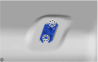
Attach the claw to install the visor holder base.
- HINT:
-
Use the same procedure for the opposite side.
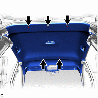
Install 5 new clips.
for Rear Pillar RH Side:
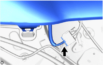
Connect the connector.
for Front Pillar RH Side:
Remove the protective cover installed to the front pillar RH.
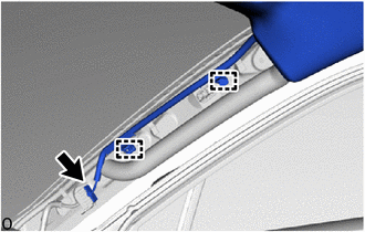
Attach the wire harness clamp.
Connect the connector.
Install the protective cover to the front pillar RH.
for Front Pillar LH Side:
Remove the protective cover installed to the front pillar LH.
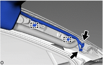
Attach the wire harness clamp.
Connect the 2 connectors.
Install the protective cover to the front pillar LH.
w/ ETC System:
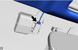
Connect the connector.
for Windshield Glass Side:

Connect each connector.
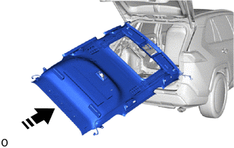
6.INSTALL ROOF HEADLINING ASSEMBLY (for Moon Roof)
|
|
Install in this Direction |
Insert the roof headlining assembly into the cabin from the back door.
- NOTICE:
- ·
Installation of the roof headlining assembly must be performed by multiple people to prevent deformation of the roof headlining assembly.
·Check that the corners of the roof headlining are not folded, twisted or otherwise deformed and that none of the mounted parts have fallen off.
·Make sure that the roof headlining does not get caught on anything as it may become bent or damaged.
·Do not damage the roof headlining or vehicle interior.
Attach the claw to install the visor holder base.
- HINT:
-
Use the same procedure for the opposite side.
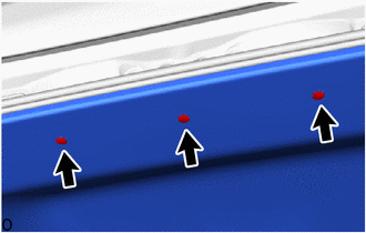
Install 3 new clips.
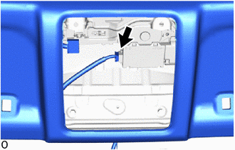
Connect the connector.
for Rear Pillar RH Side:
Connect the connector.
for Front Pillar RH Side:
Remove the protective cover installed to the front pillar RH.
Attach the wire harness clamp.
Connect the connector.
Install the protective cover to the front pillar RH.
for Front Pillar LH Side:
Remove the protective cover installed to the front pillar LH.
Attach the wire harness clamp.
Connect the 2 connectors.
Install the protective cover to the front pillar LH.
w/ ETC System:
Connect the connector.
for Windshield Glass Side:
Connect the 2 connectors.
7.INSTALL ROOF HEADLINING ASSEMBLY (for Panoramic Moon Roof)
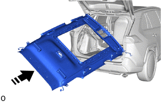
|
|
Install in this Direction |
Insert the roof headlining assembly into the cabin from the back door.
- NOTICE:
- ·
Installation of the roof headlining assembly must be performed by multiple people to prevent deformation of the roof headlining assembly.
·Check that the corners of the roof headlining are not folded, twisted or otherwise deformed and that none of the mounted parts have fallen off.
·Make sure that the roof headlining does not get caught on anything as it may become bent or damaged.
·Do not damage the roof headlining or vehicle interior.
Attach the claw to install the visor holder base.
- HINT:
-
Use the same procedure for the opposite side.
Attach the guide and fastener to install the roof headlining assembly.
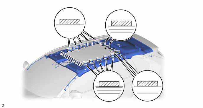
| *a | Guide | *b | Fastener |
Install 3 new clips.
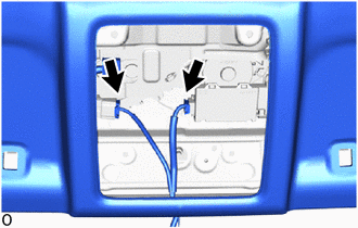
Connect the 2 connectors.
for Rear Pillar LH Side:
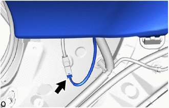
Connect the connector.
for Rear Pillar RH Side:
Connect the connector.
for Front Pillar RH Side:
Remove the protective cover installed to the front pillar RH.
Attach the wire harness clamp.
Connect the connector.
Install the protective cover to the front pillar RH.
for Front Pillar LH Side:
Remove the protective cover installed to the front pillar LH.
Attach the wire harness clamp.
Connect the 2 connectors.
Install the protective cover to the front pillar LH.
w/ ETC System:
Connect the connector.
for Windshield Glass Side:
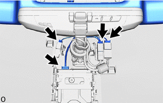
Connect each connector.
63318C
8.INSTALL SUN ROOF OPENING TRIM MOULDING (for Moon Roof)
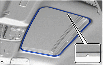
| *a | Sun Roof Opening Trim Moulding Fabric Cover |
| *b | Cutout of the Roof Headlining Assembly |
Install the sun roof opening trim moulding as shown in the illustration.
86981
9.INSTALL TOLL COLLECTION COVER (w/ ETC System)
86466D
10.INSTALL NO. 1 FORWARD RECOGNITION COVER (w/ Pre-collision System)
86466E
11.INSTALL NO. 2 FORWARD RECOGNITION COVER (w/ Pre-collision System)
81240
12.INSTALL NO. 1 ROOM LIGHT ASSEMBLY
13.INSTALL MAP LIGHT ASSEMBLY
74610A
14.INSTALL ASSIST GRIP SUB-ASSEMBLY
- HINT:
-
Use the same procedure for all assist grip sub-assemblies.
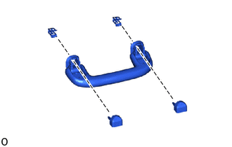
Install the 2 clips to the assist grip sub-assembly.
Temporarily install the 2 assist grip covers to the assist grip sub-assembly as shown in the illustration.
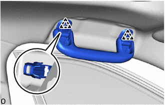
Attach the clip to install the assist grip sub-assembly.
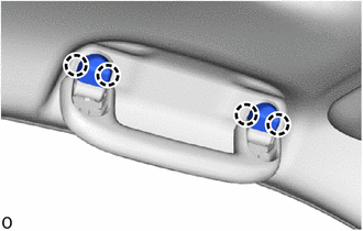
Attach the claw to install the 2 assist grip covers.
- NOTICE:
-
Check that the 2 clips are securely attached.
74630E
15.INSTALL REAR ASSIST GRIP ASSEMBLY LH
- HINT:
-
Use the same procedure as for the assist grip sub-assembly.
74620C
16.INSTALL REAR ASSIST GRIP ASSEMBLY RH
- HINT:
-
Use the same procedure as for the assist grip sub-assembly.
74348
17.INSTALL VISOR HOLDER
- HINT:
-
Use the same procedure for the opposite side.
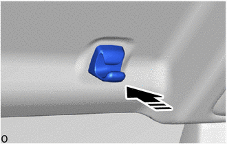
|
|
Install in this Direction |
Push in the end of the visor holder to install the visor holder.
74320
18.INSTALL VISOR ASSEMBLY LH
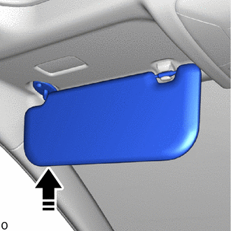
|
|
Install in this Direction |
Set the visor assembly LH into place by aligning it upward with the connector and screw fastening hole.
- NOTICE:
- ·
When setting the part into place, move it straight upward so as not to damage the connector.
·Hold the visor assembly with one hand so that it does not drop.
Connect the visor assembly LH to the visor holder LH to set it into place.
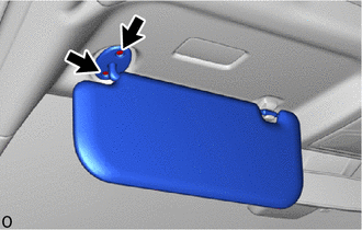
Install the visor assembly LH with the 2 screws.
74310
19.INSTALL VISOR ASSEMBLY RH
- HINT:
-
Use the same procedure described for the LH side.
62480A
20.INSTALL INNER ROOF SIDE GARNISH ASSEMBLY LH
When reusing the inner roof side garnish assembly LH:
Install 8 new clips to the inner roof side garnish assembly LH.
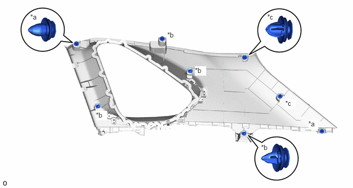
| *a | Clip A | *b | Clip B |
| *c | Clip C | - | - |
Attach the clip to install the inner roof side garnish assembly LH.
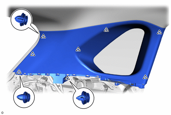
| *a | Clip A | *b | Clip B |
| *c | Clip C | - | - |
62470A
21.INSTALL INNER ROOF SIDE GARNISH ASSEMBLY RH
- HINT:
-
Use the same procedure described for the LH side.
64740E
22.INSTALL DECK TRIM SIDE PANEL ASSEMBLY LH
Attach the guide, claw and clip to install the deck trim side panel assembly LH.
except "TORX" Screw:
Install the screw.
for "TORX" Screw:
Using a T30 "TORX" socket wrench, install the "TORX" screw.
Install the clip.
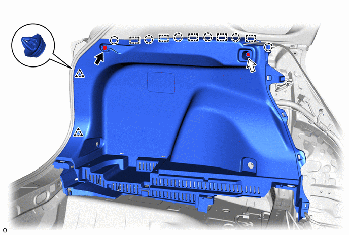

|
Clip | 
|
Screw or "TORX" Screw |
64730J
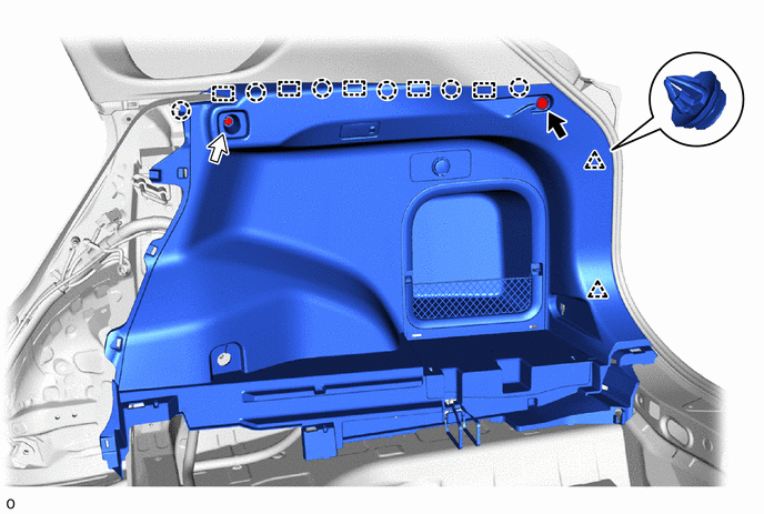
23.INSTALL DECK TRIM SIDE PANEL ASSEMBLY RH
Connect each connector.
Attach the guide, claw and clip to install the deck trim side panel assembly RH.
except "TORX" Screw:
Install the screw.
for "TORX" Screw:
Using a T30 "TORX" socket wrench, install the "TORX" screw.
Install the clip.
|
|
Clip |
|
Screw or "TORX" Screw |
58460D
24.INSTALL LUGGAGE HOLD BELT STRIKER ASSEMBLY
- HINT:
-
Use the same procedure for the opposite side.
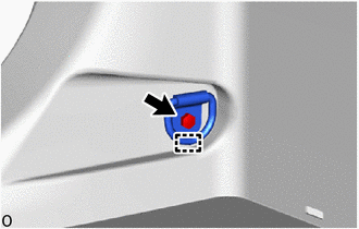
Attach the guide to install the luggage hold belt striker assembly with the bolt.
73708A
25.INSTALL TETHER ANCHOR BRACKET SET
- HINT:
-
Use the same procedure for the opposite side.
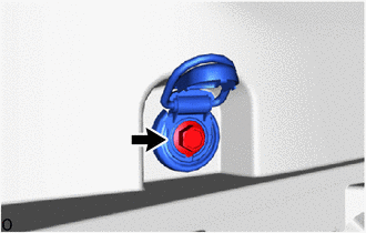
Tighten the bolt to install the tether anchor bracket set.
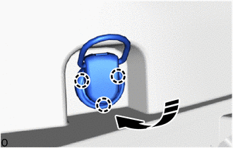
|
|
Install in this Direction |
Attach the claw as shown in the illustration.
62552F
26.INSTALL REAR SEAT SIDE GARNISH LH

|
|
Install in this Direction |
Attach the claw and clip to install the rear seat side garnish LH as shown in the illustration.
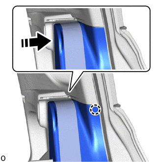
|
|
Install in this Direction |
Attach the claw as shown in the illustration.
62551F
27.INSTALL REAR SEAT SIDE GARNISH RH
- HINT:
-
Use the same procedure described for the LH side.
62412
28.INSTALL CENTER PILLAR GARNISH LH
When reusing the center pillar garnish LH:

Install a new clip.
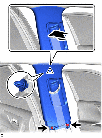
|
|
Install in this Direction |
Attach the clip to install the center pillar garnish LH as shown in the illustration.
Install the 2 clips.
62411
29.INSTALL CENTER PILLAR GARNISH RH
- HINT:
-
Use the same procedure described for the LH side.
62414A
30.INSTALL LOWER CENTER PILLAR GARNISH LH
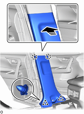
|
|
Install in this Direction |
Attach the clip and claw to install the lower center pillar garnish LH as shown in the illustration.
62413A
31.INSTALL LOWER CENTER PILLAR GARNISH RH
- HINT:
-
Use the same procedure described for the LH side.
73220
32.INSTALL FRONT SEAT OUTER BELT ASSEMBLY LH
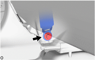
Install the front seat outer belt assembly LH with the bolt.
- Torque:
- 42 N*m (428 kgf*cm, 31 ft.*lbf)
73210
33.INSTALL FRONT SEAT OUTER BELT ASSEMBLY RH
- HINT:
-
Use the same procedure described for the LH side.
73233
34.INSTALL OUTER LAP BELT ANCHOR COVER
- HINT:
-
Use the same procedure for both outer lap belt anchor covers.
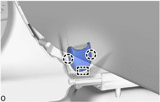
Attach the guide and claw to install the outer lap belt anchor cover.
62212
35.INSTALL FRONT PILLAR GARNISH LH
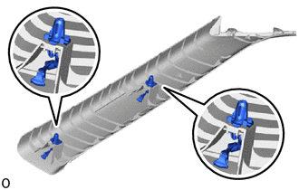
Install 2 new front pillar garnish clips to the front pillar garnish LH.
- NOTICE:
-
Make sure that the position and direction of the front pillar garnish clip is correct when installing.
Peel off the adhesive tape and remove the protective cover.
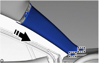
|
|
Install in this Direction |
Insert the guide in the direction indicated by the arrow shown in the illustration.
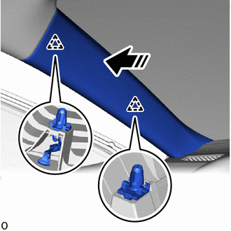
|
|
Install in this Direction |
Push in the direction indicated by the arrow shown in the illustration to attach the clip to install the front pillar garnish LH.
62211
36.INSTALL FRONT PILLAR GARNISH RH
- HINT:
-
Use the same procedure described for the LH side.
62312B
37.INSTALL FRONT DOOR OPENING TRIM WEATHERSTRIP LH
62311B
38.INSTALL FRONT DOOR OPENING TRIM WEATHERSTRIP RH
- HINT:
-
Use the same procedure described for the LH side.
62112
39.INSTALL COWL SIDE TRIM BOARD LH
62111C
40.INSTALL COWL SIDE TRIM BOARD RH
- HINT:
-
Use the same procedure described for the LH side.
67914B
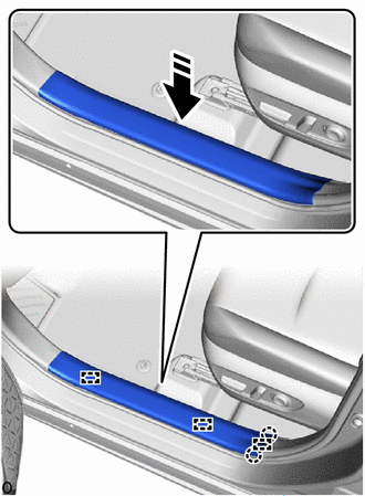
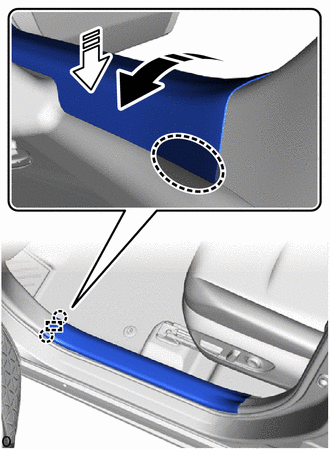
41.INSTALL FRONT DOOR SCUFF PLATE LH
|
|
Install in this Direction |
Attach the claw and align the guide in the direction indicated by the arrow shown in the illustration.

|
Place Hand Here |
|
|
Install in this Direction (1) |

|
Install in this Direction (2) |
Push in the installation direction (1) shown in the illustration to attach the claw on the vehicle exterior side and align the guide.
Place your hand at the position shown in the illustration and attach the claw while pulling in the installation direction (2) to install the front door scuff plate LH.
67913B
42.INSTALL FRONT DOOR SCUFF PLATE RH
- HINT:
-
Use the same procedure described for the LH side.
62332C
43.INSTALL REAR DOOR OPENING TRIM WEATHERSTRIP LH
62331C
44.INSTALL REAR DOOR OPENING TRIM WEATHERSTRIP RH
- HINT:
-
Use the same procedure described for the LH side.
58577E
45.INSTALL REAR NO. 1 FLOOR MAT SUPPORT SIDE PLATE
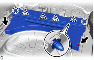
Attach the claw and clip to install the rear No. 1 floor mat support side plate with the 2 screws.
73706
46.INSTALL CHILD RESTRAINT SEAT ANCHOR BRACKET SUB-ASSEMBLY LH
73705
47.INSTALL CHILD RESTRAINT SEAT ANCHOR BRACKET SUB-ASSEMBLY RH
- HINT:
-
Use the same procedure described for the LH side.
71304C
48.INSTALL REAR SEATBACK HINGE SUB-ASSEMBLY LH
71303C
49.INSTALL REAR SEATBACK HINGE SUB-ASSEMBLY RH
- HINT:
-
Use the same procedure described for the LH side.
58464D
50.INSTALL BATTERY SERVICE COVER BOARD (for HV Model)
58467H
51.INSTALL NO. 3 BATTERY SERVICE COVER BOARD (for HV Model)
58466J
52.INSTALL NO. 2 BATTERY SERVICE COVER BOARD (for HV Model)
53.INSTALL REAR SEATBACK ASSEMBLY RH
73350C
54.INSTALL REAR CENTER SEAT OUTER BELT ASSEMBLY (FLOOR ANCHOR)
55.INSTALL REAR SEATBACK ASSEMBLY LH
58386
56.INSTALL REAR FLOOR FINISH PLATE
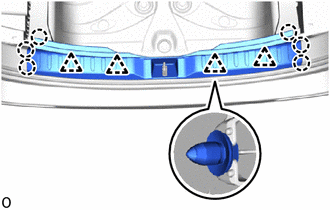
Attach the claw and clip to install the rear floor finish plate.
67918E
57.INSTALL REAR DOOR SCUFF PLATE LH
for Gasoline Model:
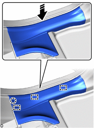
|
|
Install in this Direction |
Attach the claw and align the guide in the direction indicated by the arrow shown in the illustration.
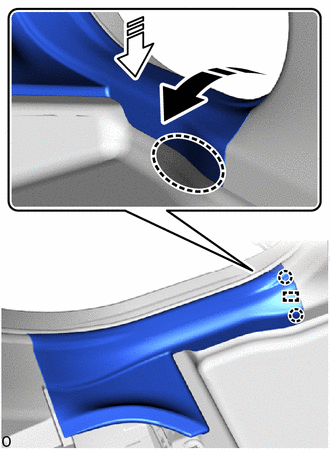
|
|
Place Hand Here |
|
|
Install in this Direction (1) |
|
|
Install in this Direction (2) |
Push in the installation direction (1) shown in the illustration to attach the claw on the vehicle exterior side and align the guide.
Place your hand at the position shown in the illustration and attach the claw while pulling in the installation direction (2) to install the rear door scuff plate LH.
for HV Model:
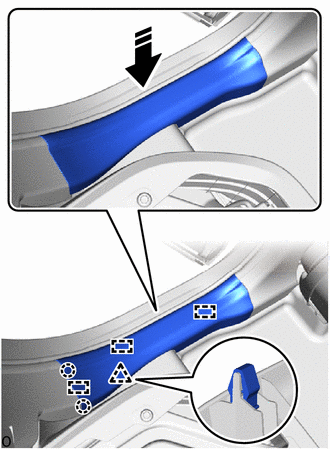
|
|
Install in this Direction |
Attach the claw and clip and align the guide in the direction indicated by the arrow shown in the illustration.
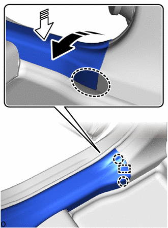
|
|
Place Hand Here |
|
|
Install in this Direction (1) |
|
|
Install in this Direction (2) |
Push in the installation direction (1) shown in the illustration to attach the claw on the vehicle exterior side and align the guide.
Place your hand at the position shown in the illustration and attach the claw while pulling in the installation direction (2) to install the rear door scuff plate LH.
67917C
58.INSTALL REAR DOOR SCUFF PLATE RH
- HINT:
-
Use the same procedure described for the LH side.
72693
59.INSTALL REAR SEAT CUSHION LOCK HOOK
60.INSTALL BENCH TYPE REAR SEAT CUSHION ASSEMBLY
64779K
61.INSTALL SPARE WHEEL COVER STOPPER
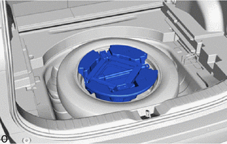
Install the spare wheel cover stopper.
58417H
62.INSTALL REAR NO. 3 FLOOR BOARD
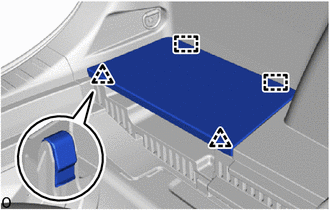
Attach the guide and clip to install the rear No. 3 floor board.
58416K
63.INSTALL REAR NO. 2 FLOOR BOARD
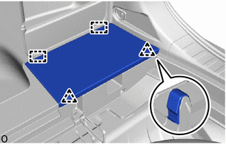
Attach the guide and clip to install the rear No. 2 floor board.
58410B
64.INSTALL DECK BOARD ASSEMBLY
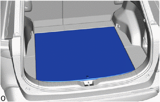
Install the deck board assembly.