EXTERIOR PANELS / TRIM GRILLE SHUTTER REASSEMBLY
PROCEDURE

 53019F
1.INSTALL RADIATOR SHUTTER SUB-ASSEMBLY
53019F
1.INSTALL RADIATOR SHUTTER SUB-ASSEMBLY
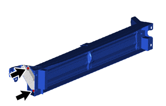
Install a new radiator shutter sub-assembly with the 2 screws.
53156F
2.INSTALL NO. 2 RADIATOR GRILLE SEAL
- HINT:
-
When installing a new No. 2 radiator grille seal, heat the radiator shutter sub-assembly using a heat light.
- Standard:
Item Temperature Radiator Shutter Sub-assembly 20 to 30°C (68 to 86°F)
- CAUTION:
-
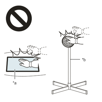 2.365,2 2.698,2 false 0.5,2.333 0.5,2.667 true 0.427,2.708 0.74,2.865 0.313,0.156 10 false *a 2.76,1.927 3.073,2.083 0.313,0.156 10 false *b
*a Heated Part *b Heat Light
- ·
Do not touch the heat light and heated parts.
·Touching the heat light may result in burns.
·Touching heated parts for a long time may result in burns.
When reusing the radiator shutter sub-assembly:
Using a heat light, heat the radiator shutter sub-assembly surface.
Remove any remaining double-sided tape from the radiator shutter sub-assembly.
Wipe off any tape adhesive residue with cleaner.
- NOTICE:
- ·
Installing the No. 2 radiator grille seal with some double-sided tape remaining may cause poor adhesion. Perform this procedure until sufficiently removed it.
·Make sure to use a cloth when removing. Using a screwdriver, etc., may cause damage and poor adhesion.
·Clean a new radiator shutter sub-assembly surface.
Remove the release paper of a new No. 2 radiator grille seal trying not to touch the adhesional surface.
Install the No. 2 radiator grille seal as shown in the illustration.
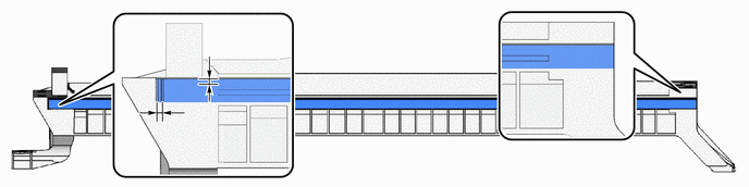
| *a | Reference Position | *b | Seal Edge Application Range |
| *c | Rib | *d | Seal Overhang Allowed |
- Standard Measurement:
Area Measurement Area Measurement A Below 3 mm (0.118 in.) B Below 3 mm (0.118 in.)
53157C
3.INSTALL NO. 3 RADIATOR GRILLE SEAL
- HINT:
-
When installing a new No. 3 radiator grille seal, heat the radiator shutter sub-assembly using a heat light.
- Standard:
Item Temperature Radiator Shutter Sub-assembly 20 to 30°C (68 to 86°F)
- CAUTION:
-
2.365,2 2.698,2 false 0.5,2.333 0.5,2.667 true 0.427,2.708 0.74,2.865 0.313,0.156 10 false *a 2.76,1.927 3.073,2.083 0.313,0.156 10 false *b
*a Heated Part *b Heat Light
- ·
Do not touch the heat light and heated parts.
·Touching the heat light may result in burns.
·Touching heated parts for a long time may result in burns.
When reusing the radiator shutter sub-assembly:
Using a heat light, heat the radiator shutter sub-assembly surface.
Remove any remaining double-sided tape from the radiator shutter sub-assembly.
Wipe off any tape adhesive residue with cleaner.
- NOTICE:
- ·
Installing the No. 3 radiator grille seal with some double-sided tape remaining may cause poor adhesion. Perform this procedure until sufficiently removed it.
·Make sure to use a cloth when removing. Using a screwdriver, etc., may cause damage and poor adhesion.
·Clean a new radiator shutter sub-assembly surface.
Remove the release paper of a new No. 3 radiator grille seal trying not to touch the adhesional surface.
Install the No. 3 radiator grille seal as shown in the illustration.
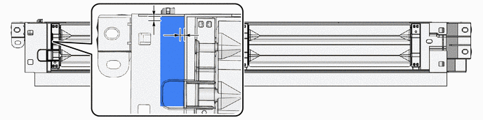
| *a | Reference Position | *b | Seal Edge Application Range |
| *c | Rib | - | - |
- Standard Measurement:
Area Measurement Area Measurement A Below 3 mm (0.118 in.) B Below 3 mm (0.118 in.)
53155C
4.INSTALL NO. 1 RADIATOR GRILLE SEAL
- HINT:
-
When installing a new No. 1 radiator grille seal, heat the radiator shutter sub-assembly using a heat light.
- Standard:
Item Temperature Radiator Shutter Sub-assembly 20 to 30°C (68 to 86°F)
- CAUTION:
-
2.365,2 2.698,2 false 0.5,2.333 0.5,2.667 true 0.427,2.708 0.74,2.865 0.313,0.156 10 false *a 2.76,1.927 3.073,2.083 0.313,0.156 10 false *b
*a Heated Part *b Heat Light
- ·
Do not touch the heat light and heated parts.
·Touching the heat light may result in burns.
·Touching heated parts for a long time may result in burns.
When reusing the radiator shutter sub-assembly:
Using a heat light, heat the radiator shutter sub-assembly surface.
Remove any remaining double-sided tape from the radiator shutter sub-assembly.
Wipe off any tape adhesive residue with cleaner.
- NOTICE:
- ·
Installing the No. 1 radiator grille seal with some double-sided tape remaining may cause poor adhesion. Perform this procedure until sufficiently removed it.
·Make sure to use a cloth when removing. Using a screwdriver, etc., may cause damage and poor adhesion.
·Clean a new radiator shutter sub-assembly surface.
Remove the release paper of a new No. 1 radiator grille seal trying not to touch the adhesional surface.
Install the No. 1 radiator grille seal as shown in the illustration.
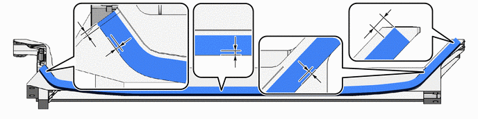
| *a | Reference Position | *b | Seal Edge Application Range |
| *c | Rib | *d | Mark-off Line |
| *e | Seal No Overhang Allowed | - | - |
- Standard Measurement:
Area Measurement Area Measurement A Below 3 mm (0.118 in.) B Below 3 mm (0.118 in.) C Below 3 mm (0.118 in.) D Below 3 mm (0.118 in.) E Below 10 mm (0.394 in.) - -
82090B
5.INSTALL EXTENSION WIRE ASSEMBLY
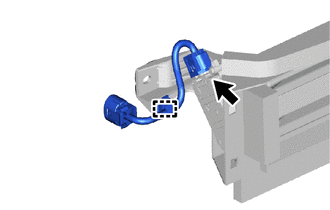
Attach the clamp to install the extension wire assembly.
Connect the connector.
88790B
6.INSTALL THERMISTOR ASSEMBLY