EXTERIOR PANELS / TRIM REAR BUMPER(for Type A) REASSEMBLY
PROCEDURE

 52023
1.INSTALL REAR BUMPER REINFORCEMENT SUB-ASSEMBLY
52023
1.INSTALL REAR BUMPER REINFORCEMENT SUB-ASSEMBLY
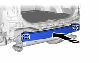

|
Install in this Direction |
Attach the guide to set the rear bumper reinforcement sub-assembly.
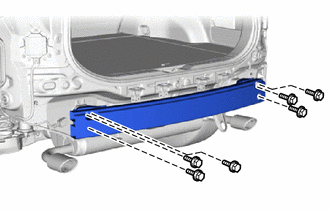
Install the rear bumper reinforcement sub-assembly with the 6 bolts.
- Torque:
- 29 N*m (296 kgf*cm, 21 ft.*lbf)
52156A
2.INSTALL REAR BUMPER SIDE SUPPORT LH
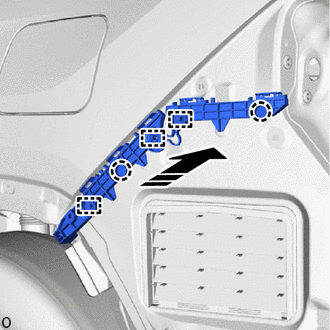
|
|
Install in this Direction |
Attach the guide and claw to install the rear bumper side support LH.
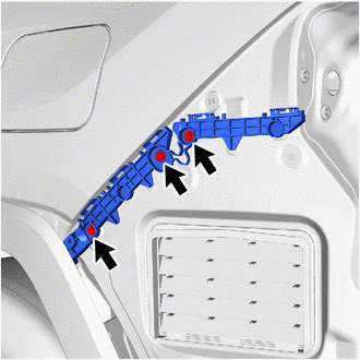
Install the 3 screws.
52155A
3.INSTALL REAR BUMPER SIDE SUPPORT RH
- HINT:
-
Use the same procedure described for the LH side.
52563A
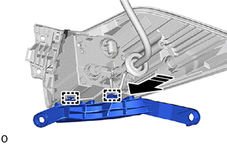
4.INSTALL REAR BUMPER UPPER RETAINER LH
|
|
Install in this Direction |
Attach the guide and install the rear bumper upper retainer LH to the rear combination light assembly LH.
52562B
5.INSTALL REAR BUMPER UPPER RETAINER RH
- HINT:
-
Use the same procedure described for the LH side.
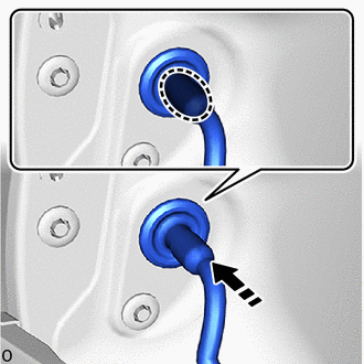
6.INSTALL REAR COMBINATION LIGHT ASSEMBLY LH

|
Place Hand Here |
|
|
Install in this Direction |
Place your hands at the position shown in the illustration, pass the wire harness into the vehicle and install the grommet.
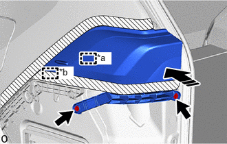
| *a | Pin |
| *b | Guide |
|
|
Push in this Direction |
Align the guide and pin to set the rear combination light assembly LH.
Push the rear combination light assembly LH towards the vehicle front to attach the pin and guide.
Install the 2 screws.
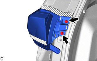
Install the 2 screws.

Insert your hand between the deck trim side panel assembly LH and the body and connect the connector.
7.INSTALL REAR COMBINATION LIGHT ASSEMBLY RH
- HINT:
-
Use the same procedure described for the LH side.
64740E
8.INSTALL DECK TRIM SIDE PANEL ASSEMBLY LH
Return the rear side of the deck trim side panel assembly LH to its original position.
64730J
9.INSTALL DECK TRIM SIDE PANEL ASSEMBLY RH
Return the rear side of the deck trim side panel assembly RH to its original position.
58460D
10.INSTALL LUGGAGE HOLD BELT STRIKER ASSEMBLY
58386
11.INSTALL REAR FLOOR FINISH PLATE
65351A
12.INSTALL BATTERY HOLE COVER (for HV Model)
58417H
13.INSTALL REAR NO. 3 FLOOR BOARD
58416K
14.INSTALL REAR NO. 2 FLOOR BOARD
76829A
15.INSTALL BACK DOOR GARNISH RETAINER
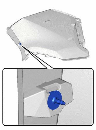
Install the back door garnish retainer.
- HINT:
-
Use the same procedure on the other side.
52461F
16.INSTALL REAR BUMPER CENTER PAD
- HINT:
-
When installing the rear bumper center pad, heat the rear bumper cover and rear bumper center pad using a heat light.
- Standard:
Item Temperature Rear Bumper Cover 20 to 30°C (68 to 86°F) Rear Bumper Center Pad 20 to 30°C (68 to 86°F)
- CAUTION:
-
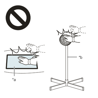 2.365,2 2.698,2 false 0.5,2.333 0.5,2.667 true 0.427,2.708 0.74,2.865 0.313,0.156 10 false *a 2.76,1.927 3.073,2.083 0.313,0.156 10 false *b
*a Heated Part *b Heat Light
- ·
Do not touch the heat light and heated parts.
·Touching the heat light may result in burns.
·Touching heated parts for a long time may result in burns.
- NOTICE:
-
Do not heat the rear bumper cover and rear bumper center pad excessively.
When reusing the rear bumper cover:
Using a heat light, heat the rear bumper cover surface.
Remove any remaining double-sided tape from the rear bumper cover.
Wipe off any tape adhesive residue with cleaner.
- NOTICE:
- ·
Installing the rear bumper center pad with any double-sided tape remaining may cause poor adhesion. Perform this procedure until the tape is sufficiently removed.
·Make sure to use a cloth when removing. Using a screwdriver, etc., may cause damage and poor adhesion.
Apply primer to the rear bumper cover on the installation area of the rear bumper center pad using a brush or felt.
- NOTICE:
- ·
Replace the brush or felt if it is dirty or has become hardened.
·Keep any painted surface free from primer.
·If the primer contacts a painted surface, it may leave light primer marks. Therefore, use protective tape when using liquid primer.
·Do not touch surfaces to which primer has been applied until the rear bumper center pad has been attached.
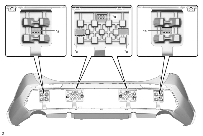
| *a | Mark-off Line | - | - |

|
Primer | - | - |
Let the primer dry sufficiently.
- NOTICE:
-
Do not touch applied surfaces until the primer is dry.
- Recommended drying time:
10 minutes or more (at 23°C (73°F))
Using a heat light, heat the rear bumper cover and a new rear bumper center pad.
- NOTICE:
-
Do not heat the rear bumper cover and rear bumper center pad excessively.
Remove the release paper of the new rear bumper center pad trying not to touch the adhesional surface.
- NOTICE:
-
After removing the release paper, keep the exposed adhesive free from foreign matter.
Align the rear bumper center pad with the mark-off line on the rear bumper cover and install it.
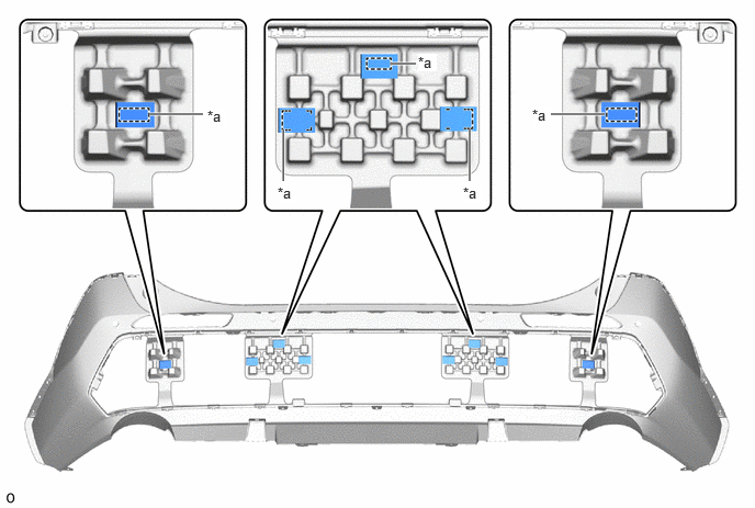
| *a | Mark-off Line | - | - |
- NOTICE:
-
The application strength of the rear bumper center pad will weaken if reapplied. If reapplication is necessary, be sure to replace it with a new one.
- HINT:
-
Press the rear bumper center pad firmly to install it.
52453
17.INSTALL REAR BUMPER CENTER GUARD
Attach the guide and claw to install the rear bumper center guard.
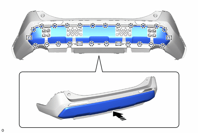
|
|
Install in this Direction | - | - |
Install the 4 outside moulding retainers as shown in the illustration.
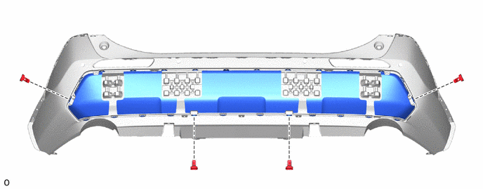
81490C
18.INSTALL REAR FOG LIGHT ASSEMBLY LH
81480A
19.INSTALL REAR FOG LIGHT ASSEMBLY RH
- HINT:
-
Use the same procedure described for the LH side.
20.INSTALL SPRING NUT

|
|
Install in this Direction |
Install the 2 spring nuts.
- HINT:
-
Use the same procedure on the other side.
52162A
21.INSTALL REAR BUMPER PIECE LH
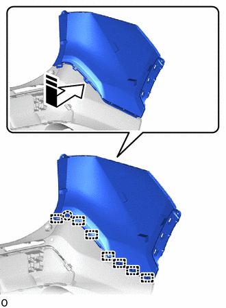
|
|
Install in this Direction |
Attach the guide and claw to install the rear bumper piece LH.
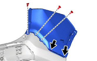
Install the 3 outside moulding retainers as shown in the illustration.
Install the 2 screws.
52161A
22.INSTALL REAR BUMPER PIECE RH
- HINT:
-
Use the same procedure described for the LH side.
82182
23.INSTALL NO. 2 LUGGAGE ROOM WIRE
Attach the clamp to install the No. 2 luggage room wire.
Connect the 2 connectors.

| *A | w/ TOYOTA Parking Assist-sensor System | *B | w/ Hands Free Power Back Door |
89348S
24.INSTALL REAR CENTER ULTRASONIC SENSOR RETAINER (w/ TOYOTA Parking Assist-sensor System)
89348R
25.INSTALL REAR CORNER ULTRASONIC SENSOR RETAINER (w/ TOYOTA Parking Assist-sensor System)
89342A
26.INSTALL REAR CENTER ULTRASONIC SENSOR (w/ TOYOTA Parking Assist-sensor System)
89342
27.INSTALL REAR CORNER ULTRASONIC SENSOR (w/ TOYOTA Parking Assist-sensor System)
891B1
28.INSTALL KICK DOOR CONTROL BRACKET (w/ Hands Free Power Back Door)