EXTERIOR PANELS / TRIM FRONT BUMPER(for Type A) REASSEMBLY
PROCEDURE

 52103C
1.INSTALL FRONT BUMPER EXTENSION SUB-ASSEMBLY LH
52103C
1.INSTALL FRONT BUMPER EXTENSION SUB-ASSEMBLY LH


|
Bolt A |

|
Bolt B |

|
Nut |
Install the front bumper extension sub-assembly LH with the 2 nuts and 2 bolts.
- Torque:
- for Bolt A : 135 N*m (1377 kgf*cm, 100 ft.*lbf)
- for Bolt B : 9.5 N*m (97 kgf*cm, 84 in.*lbf)
- for Nut : 12.5 N*m (127 kgf*cm, 9 ft.*lbf)
52102F
2.INSTALL FRONT BUMPER EXTENSION SUB-ASSEMBLY RH
- HINT:
-
Use the same procedure described for the LH side.
52618
3.INSTALL FRONT BUMPER LOWER ABSORBER (for HV Model)
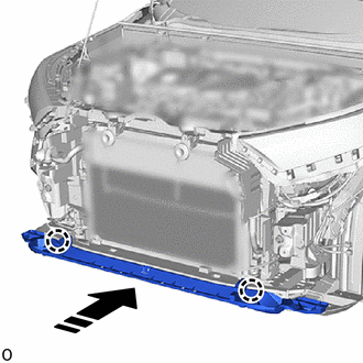

|
Install in this Direction |
Attach the claw to install the front bumper lower absorber as shown in the illustration.
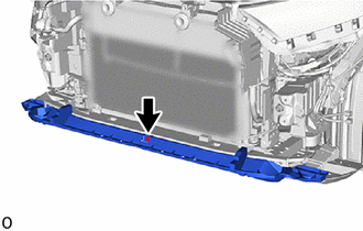
Install the clip.
52618
4.INSTALL FRONT BUMPER LOWER ABSORBER (for Gasoline Model)
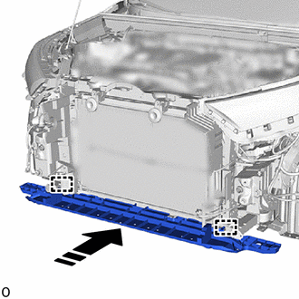
|
|
Install in this Direction |
Attach the guide and install the front bumper lower absorber as shown in the illustration.
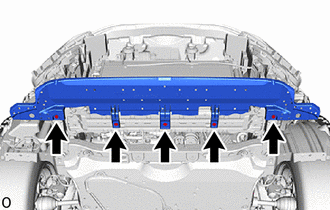
Install the 5 bolts.
51441
5.INSTALL NO. 1 ENGINE UNDER COVER
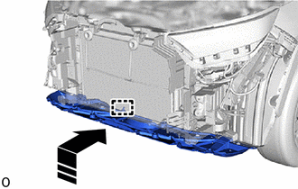
|
|
Install in this Direction |
Attach the guide to install the No. 1 engine under cover.
Install the 2 screws and 2 bolts.
- Torque:
- for Bolt : 7.5 N*m (76 kgf*cm, 66 in.*lbf)
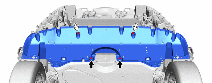
|
|
Bolt |
|
Screw |
52132A
6.INSTALL FRONT BUMPER NO. 2 REINFORCEMENT (for HV Model)
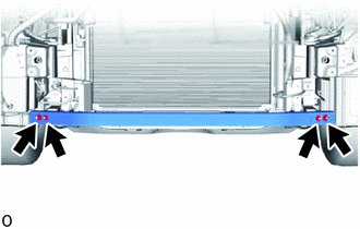
Install the front bumper No. 2 reinforcement with the 4 nuts.
- Torque:
- 18 N*m (184 kgf*cm, 13 ft.*lbf)
52021
7.INSTALL FRONT BUMPER REINFORCEMENT SUB-ASSEMBLY
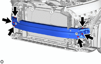
Install the front bumper reinforcement sub-assembly with the 6 bolts.
- Torque:
- 43 N*m (438 kgf*cm, 32 ft.*lbf)
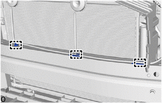
Attach the wire harness clamp.
52614
8.INSTALL FRONT BUMPER NO. 2 ENERGY ABSORBER
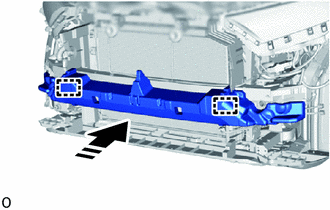
|
|
Install in this Direction |
Attach the guide and install the front bumper No. 2 energy absorber.
52536
9.INSTALL FRONT BUMPER SIDE RETAINER LH
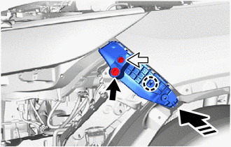
|
|
Install in this Direction |
|
|
Bolt |
|
|
Screw |
Attach the claw to install the front bumper side retainer LH as shown in the illustration.
Install the screw.
Install the bolt.
52535
10.INSTALL FRONT BUMPER SIDE RETAINER RH
- HINT:
-
Use the same procedure described for the LH side.
53112E
11.INSTALL LOWER NO. 1 RADIATOR GRILLE
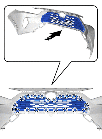
|
|
Install in this Direction |
Attach the claw and guide to install the lower No. 1 radiator grille as shown in the illustration.
53113E
12.INSTALL LOWER NO. 2 RADIATOR GRILLE
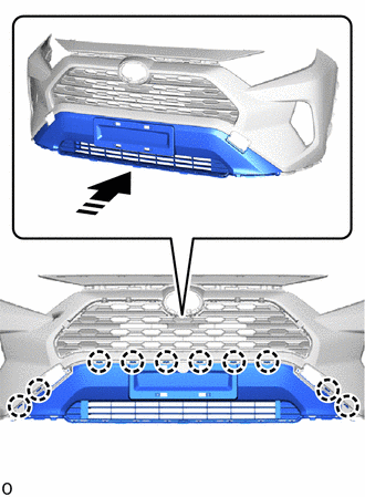
|
|
Install in this Direction |
Attach the claw and install the lower No. 2 radiator grille as shown in the illustration.
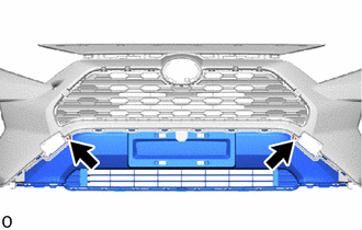
Install the 2 screws.
52711
13.INSTALL FRONT BUMPER MOULDING (for Separate Type)

|
|
Install in this Direction |
Attach the claw and install the front bumper moulding as shown in the illustration.
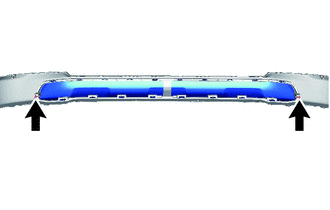
Install the 2 screws.
52411
14.INSTALL FRONT BUMPER GUARD
Attach the claw and guide to install the front bumper guard as shown in the illustration.
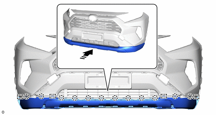
|
|
Install in this Direction | - | - |
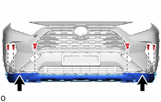
Install the 6 outside moulding retainers as shown in the illustration.
Install the 2 screws.
52438
15.INSTALL FRONT BUMPER GUARD COVER LH
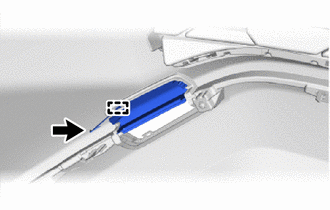
|
|
Fall Prevention Hook |
Connect the fall prevention hook as shown in the illustration.
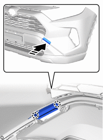
|
|
Install in this Direction |
Attach the claw and install the front bumper guard cover LH as shown in the illustration.
52437
16.INSTALL FRONT BUMPER GUARD COVER RH
- HINT:
-
Use the same procedure described for the LH side.
17.INSTALL FRONT BUMPER ARM HOLE COVER LH
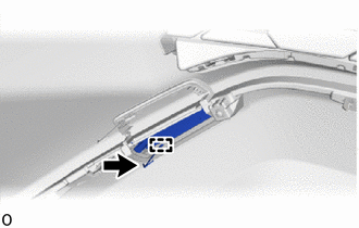
|
|
Fall Prevention Hook |
Connect the fall prevention hook as shown in the illustration.
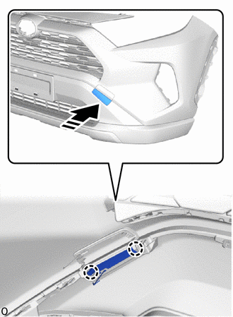
|
|
Install in this Direction |
Attach the claw and install the front bumper arm hole cover LH as shown in the illustration.
18.INSTALL FRONT BUMPER ARM HOLE COVER RH
- HINT:
-
Use the same procedure described for the LH side.
75311
19.INSTALL RADIATOR GRILLE EMBLEM (w/ Dynamic Radar Cruise Control System)
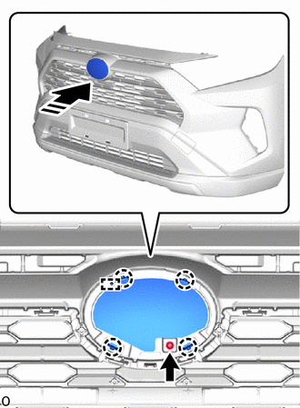
|
|
Install in this Direction |
Attach the claw and guide to install the radiator grille emblem as shown in the illustration.
Install the screw.
20.INSTALL RADIATOR GRILLE EMBLEM SUB-ASSEMBLY (w/o Dynamic Radar Cruise Control System)
- HINT:
-
Use the same procedure described for the radiator grille emblem (w/ Dynamic Radar Cruise Control System).
52128B
21.INSTALL FRONT BUMPER HOLE COVER LH
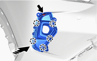
|
|
Install in this Direction |
Attach the claw and install the front bumper hole cover LH.
Install the clip.
52127D
22.INSTALL FRONT BUMPER HOLE COVER RH
- HINT:
-
Use the same procedure described for the LH side.
53124B
23.INSTALL SIDE RADIATOR GRILLE MOULDING LH

|
|
Install in this Direction |
Attach the claw and install the side radiator grille moulding LH as shown in the illustration.
53123B
24.INSTALL SIDE RADIATOR GRILLE MOULDING RH
- HINT:
-
Use the same procedure described for the LH side.
53115B
25.INSTALL RADIATOR GRILLE BRACKET
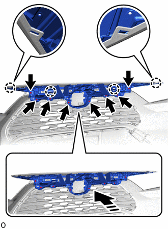
|
|
Install in this Direction |
Attach the claw and install the radiator grille bracket as shown in the illustration.
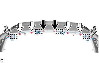
Install the 8 screws.
|
|
Screw |
|
|
Clip (A) |
|
|
Clip (B) |
Attach the guide and install the 2 clips (B).
Install the 4 clips (A).
Install the 2 screws.
53395E
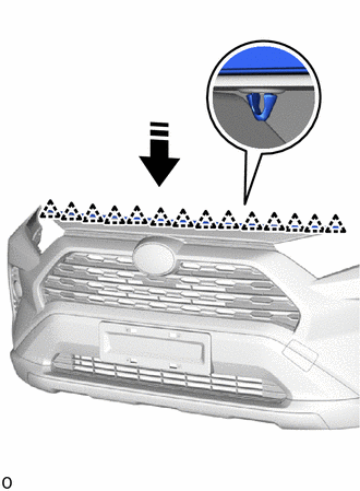
26.INSTALL FRONT HOOD TO END PANEL SEAL
|
|
Install in this Direction |
Attach the clip and install the front hood to end panel seal as shown in the illustration.
81220
27.INSTALL FOG LIGHT ASSEMBLY LH
81210A
28.INSTALL FOG LIGHT ASSEMBLY RH
- HINT:
-
Use the same procedure described for the LH side.
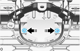
29.INSTALL NUT (w/ Dynamic Radar Cruise Control System)
|
|
Install in this Direction |
Install the 2 nuts as shown in the illustration.
88211B
30.INSTALL MILLIMETER WAVE RADAR SENSOR ASSEMBLY (w/ Dynamic Radar Cruise Control System)
86790B
31.INSTALL FRONT TELEVISION CAMERA ASSEMBLY (w/ Panoramic View Monitor System)
89341L
32.INSTALL FRONT CENTER ULTRASONIC SENSOR (w/ TOYOTA Parking Assist-sensor System)
89341K
33.INSTALL FRONT CORNER ULTRASONIC SENSOR (w/ TOYOTA Parking Assist-sensor System)
82114
34.INSTALL NO. 4 ENGINE ROOM WIRE
Connect each connector.
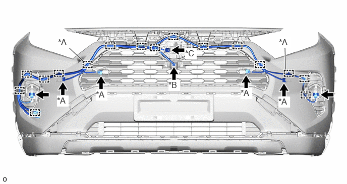
| *A | w/ TOYOTA Parking Assist-sensor System | *B | w/ Panoramic View Monitor System |
| *C | w/ Dynamic Radar Cruise Control System | - | - |
Attach the clamp and install the No. 4 engine room wire.
35.INSTALL FOG LIGHT SEAL (w/o TOYOTA Parking Assist-sensor System)
- HINT:
- ·
Use the same procedure for the RH and LH sides.
·The procedure listed below is for the LH side.
·When installing the fog light seal, heat the front bumper assembly using a heat light.
- Standard:
Item Temperature Front Bumper Assembly 20 to 30°C (68 to 86°F)
- CAUTION:
-
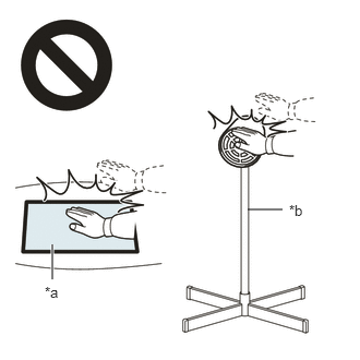 2.365,2 2.698,2 false 0.5,2.333 0.5,2.667 true 0.427,2.708 0.74,2.865 0.313,0.156 10 false *a 2.76,1.927 3.073,2.083 0.313,0.156 10 false *b
*a Heated Part *b Heat Light
- ·
Do not touch the heat light and heated parts.
·Touching the heat light may result in burns.
·Touching heated parts for a long time may result in burns.
When reusing the front bumper cover:
Using a heat light, heat the front bumper cover surface.
Remove any remaining double-sided tape from the front bumper assembly.
Wipe off any tape adhesive residue with cleaner.
- NOTICE:
- ·
Installing the fog light seal with any double-sided tape remaining may cause poor adhesion. Perform this procedure until the tape is sufficiently removed.
·Make sure to use a cloth when removing. Using a screwdriver, etc., may cause damage and poor adhesion.
·Also, clean the surface of the new front bumper cover.
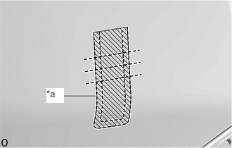
| *a | Mark-off Line |

|
Primer |
Apply primer to the front bumper assembly on the installation area of the fog light seal using a brush or felt.
- NOTICE:
- ·
Replace the brush or felt if it is dirty or has become hardened.
·Keep any painted surface free from primer.
·If the primer contacts a painted surface, it may leave light primer marks. Therefore, use protective tape when using liquid primer.
·Do not touch surfaces to which primer has been applied until the fog light seal has been attached.
Let the primer dry sufficiently.
- NOTICE:
-
Do not touch applied surfaces until the primer is dry.
- Recommended drying time:
10 minutes or more (at 23°C (73°F))
Remove the release paper of a new fog light seal trying not to touch the adhesional surface.
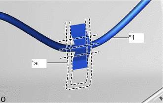
| *1 | No. 4 Engine Room Wire |
| *a | Mark-off Line |
Install the No. 4 engine room wire in the position shown in the illustration.
Install the fog light seal in the position shown in the illustration.