PARK ASSIST / MONITORING PANORAMIC VIEW MONITOR SYSTEM TERMINALS OF ECU
PARKING ASSIST ECU
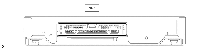
Disconnect the N62 parking assist ECU connector.
Measure the voltage and resistance according to the value(s) in the table below.
| Terminal No. (Symbol) | Terminal Description | Condition | Specified Condition |
|---|---|---|---|
| N62-1 (+B) -Body ground | Power source signal | Always | 11 to 14 V |
| N62-21 (IG) - Body ground | IG power source signal | Ignition switch ON | 11 to 14 V |
| Ignition switch off | Below 1 V | ||
| N62-2 (GND1) - Body ground | Ground | Always | Below 1 Ω |
Reconnect the N62 parking assist ECU connector.
Measure the voltage and resistance according to the value(s) in the table below.
| Terminal No. (Symbol) | Terminal Description | Condition | Specified Condition |
|---|---|---|---|
| N62-22 (REV) - Body ground | Reverse signal input | Ignition switch ON, shift lever in R | 11 to 14 V |
| Ignition switch ON, shift lever except R | Below 1 V | ||
| N62-39 (CANH) | CAN communication line | - | - |
| N62-40 (CANL) | CAN communication line | - | - |
| N62-15 (BLSW) - Body ground | Panoramic view monitor switch signal | Ignition switch ON, panoramic view monitor switch (combination switch assembly) off | 5.5 to 6.5 V |
| Ignition switch ON, panoramic view monitor switch (combination switch assembly) on | Below 1 V | ||
| N62-5 (RSW+) - Body ground | Terminal required by law | Panoramic image being displayed | 0 to 2 V |
| Panoramic image not being displayed | 5.5 to 7.05 V | ||
| N62-35 (LCB+) - N62-12 (LGND) | Power source to side television camera assembly LH | Ignition switch ON | 5.5 to 7.05 V |
| N62-36 (LCV+) - N62-12 (LGND) | Side television camera assembly LH display signal input | Ignition switch ON, panoramic view monitor switch (combination switch assembly) on, camera lens not covered, displaying image | Pulse generation (See waveform 1) |
| Ignition switch ON, panoramic view monitor switch (combination switch assembly) on, camera lens covered, blacking out screen | Pulse generation (See waveform 2) | ||
| N62-13 (LCV-) - Body ground | Side television camera assembly LH display ground | Always | Below 1 Ω |
| N62-12 (LGND) - Body ground | Side television camera assembly LH ground | Always | Below 1 Ω |
| N62-14 (SGND) - Body ground | Side television camera assembly LH ground (shield) | Always | Below 1 Ω |
| N62-27 (BCB+) - N62-28 (BGND) | Power source to front television camera | Ignition switch ON | 5.5 to 7.05 V |
| N62-29 (BCV+) - N62-28 (BGND) | Front television camera assembly display signal input | Waveform 1: Ignition switch ON, panoramic view monitor switch (combination switch assembly) on, camera lens not covered, displaying image | Pulse generation (See waveform 1) |
| Waveform 2: Ignition switch ON, panoramic view monitor switch (combination switch assembly) on, camera lens covered, blacking out screen | Pulse generation (See waveform 2) | ||
| N62-30 (BCV-) - Body ground | Front television camera assembly display ground | Always | Below 1 Ω |
| N62-28 (BGND) - Body ground | Front television camera assembly ground | Always | Below 1 Ω |
| N62-31 (SGND) - Body ground | Front television camera assembly ground (shield) | Always | Below 1 Ω |
| N62-24 (RCB+) - N62-8 (RGND) | Power source to side television camera assembly RH | Ignition switch ON | 5.5 to 7.05 V |
| N62-25 (RCV+) - N62-8 (RGND) | Side television camera assembly RH display signal input | Waveform 1: Ignition switch ON, panoramic view monitor switch (combination switch assembly) on, camera lens not covered, displaying image | Pulse generation (See waveform 1) |
| Waveform 2: Ignition switch ON, panoramic view monitor switch (combination switch assembly) on, camera lens covered, blacking out screen | Pulse generation (See waveform 2) | ||
| N62-9 (RCV-) - Body ground | Side television camera assembly RH display ground | Always | Below 1 Ω |
| N62-8 (RGND) - Body ground | Side television camera assembly RH ground | Always | Below 1 Ω |
| N62-26 (SGND)- Body ground | Side television camera assembly RH ground (shield) | Always | Below 1 Ω |
| N62-32 (CB+) - N62-33 (CGND) | Power source to rear television camera assembly | Ignition switch ON | 5.5 to 7.05 V |
| N62-10 (CV+) - N62-33 (CGND) | Rear television camera assembly display signal input | Ignition switch ON, panoramic view monitor switch (combination switch assembly) on, camera lens not covered, displaying image | Pulse generation (See waveform 1) |
| Ignition switch ON, panoramic view monitor switch (combination switch assembly) on, camera lens covered, blacking out screen | Pulse generation (See waveform 2) | ||
| N62-34 (CV-) - Body ground | Rear television camera assembly display ground | Always | Below 1 Ω |
| N62-33 (CGND) - Body ground | Rear television camera assembly ground | Always | Below 1 Ω |
| N62-11 (SGND) - Body ground | Rear television camera assembly ground (shield) | Always | Below 1 Ω |
| N62-23 (NS+) - N62-6 (NS-) | Video signal | Ignition switch ON, panoramic view monitor switch (combination switch assembly) on, camera lens not covered, displaying image | Pulse generation (See waveform 3) |
| N62-6 (NS-) - Body ground | Video ground | Always | Below 1 Ω |
| N62-7 (NSG) - Body ground | Shield ground | Always | Below 1 Ω |
Using an oscilloscope, check the waveform.
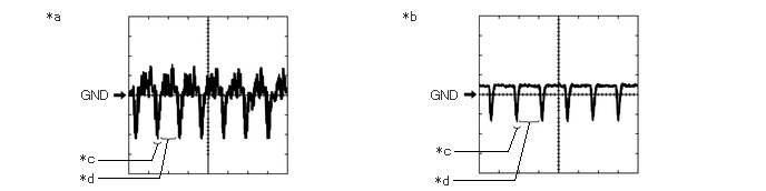
| *a | Waveform 1 | *b | Waveform 2 |
| *c | Synchronization Signal | *d | Video Waveform |
Waveform 1, 2
| Item | Content |
|---|---|
| Measurement terminal | ·
N62-36 (LCV+) - N62-12 (LGND) ·
N62-10 (CV+) - N62-33 (CGND) ·
N62-29 (BCV+) - N62-28 (BGND) ·
N62-25 (RCV+) - N62-8 (RGND) |
| Measurement setting | 200 mV/DIV., 50 μsec./DIV. |
| Condition | ·
Waveform 1: Ignition switch ON, panoramic view monitor switch (combination switch assembly) on, camera lens not covered, displaying image ·
Waveform 2: Ignition switch ON, panoramic view monitor switch (combination switch assembly) on, camera lens covered, blacking out screen |
- HINT:
- ·
The video waveform changes according to the image sent by the television camera assembly.
·The video waveform is constantly output when the ignition switch is ACC.
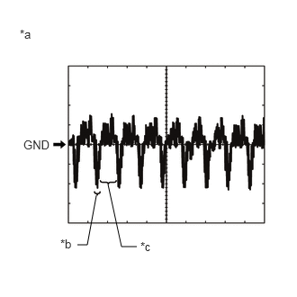
| *a | Waveform 3 (camera lens is not covered, displaying an image) |
| *b | Synchronization Signal |
| *c | Video Waveform |
Waveform 3
| Item | Content |
|---|---|
| Measurement terminal | N62-23 (NS+) - N62-6 (NS-) |
| Measurement setting | 200 mV/DIV., 50 μs./DIV. |
| Condition | Ignition switch ON, panoramic view monitor switch (combination switch assembly) on, camera lens not covered, displaying image |
- HINT:
-
The video waveform changes according to the image sent by the parking assist ECU.
RADIO AND DISPLAY RECEIVER ASSEMBLY (w/ Audio and Visual System)
NAVIGATION RECEIVER ASSEMBLY (w/ Navigation System)