K121F CVT OIL PAN INSTALLATION
PROCEDURE

 35015Y
1.INSTALL TRANSAXLE SIDE COVER SUB-ASSEMBLY
35015Y
1.INSTALL TRANSAXLE SIDE COVER SUB-ASSEMBLY

|
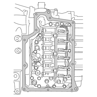
Area to be Cleaned |
Clean the transaxle side cover sub-assembly installation surface of the transaxle case sub-assembly.
- NOTICE:
-
Completely remove any oil or grease from the contact surfaces of the transaxle case sub-assembly.
Coat a new O-ring with Toyota Genuine CVT fluid FE and install it to a new transaxle side cover sub-assembly.
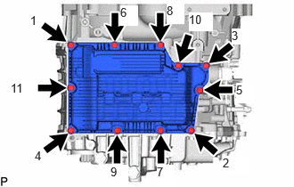
Temporarily install the transaxle side cover sub-assembly to the transaxle case sub-assembly with the 11 bolts.
Tighten the 11 bolts in the order shown in the illustration.
- Torque:
- 7.4 N*m (75 kgf*cm, 65 in.*lbf)
32901L
2.INSTALL OIL COOLER ELBOW SUB-ASSEMBLY
32941R
3.INSTALL OIL COOLER INLET HOSE
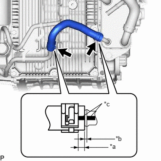
| *a | 2 to 7 mm (0.0787 to 0.275 in.) |
| *b | 0 to 3 mm (0 to 0.118 in.) |
| *c | Paint Mark |
Install the oil cooler inlet hose to the transmission oil cooler and oil cooler elbow sub-assembly, and slide the 2 hose clips to secure the hose.
- NOTICE:
- ·
Make sure to slide the oil cooler inlet hose until it contacts the hose stopper of the transmission oil cooler and oil cooler elbow sub-assembly.
·Make sure to align the paint mark of the oil cooler inlet hose with the paint mark of the transmission oil cooler and oil cooler elbow sub-assembly.
32942N
4.INSTALL NO. 1 OIL COOLER OUTLET HOSE
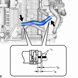
| *a | 2 to 7 mm (0.0787 to 0.275 in.) |
| *b | 0 to 3 mm (0 to 0.118 in.) |
| *c | Paint Mark |
Install the No. 1 oil cooler outlet hose to the transmission oil cooler and oil cooler elbow sub-assembly and slide the 2 hose clips to secure the hose.
- NOTICE:
- ·
Make sure to slide the No. 1 oil cooler outlet hose until it contacts the hose stopper of the transmission oil cooler and oil cooler elbow sub-assembly.
·Make sure to align the paint mark of the No. 1 oil cooler outlet hose with the paint mark of the transmission oil cooler and oil cooler elbow sub-assembly.
16261G
5.CONNECT NO. 1 WATER BY-PASS HOSE
12361
6.INSTALL FRONT ENGINE MOUNTING INSULATOR
82121
7.CONNECT ENGINE WIRE

Attach the 3 clamps to connect the engine wire to the continuously variable transaxle assembly.
Connect the engine wire to the continuously variable transaxle assembly with the bolt.
- Torque:
- 10 N*m (102 kgf*cm, 7 ft.*lbf)
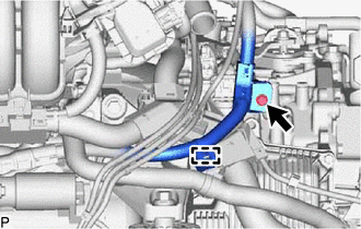
Attach the clamp.
Connect the engine wire to the continuously variable transaxle assembly with the bolt.
- Torque:
- 10 N*m (102 kgf*cm, 7 ft.*lbf)
74404B
8.INSTALL BATTERY CLAMP SUB-ASSEMBLY
89661
9.INSTALL ECM
10.INSTALL AIR CLEANER ASSEMBLY WITH AIR CLEANER HOSE
17751
11.INSTALL NO. 1 INLET AIR CLEANER
12601B
12.INSTALL NO. 1 ENGINE COVER SUB-ASSEMBLY
13.INSTALL BATTERY
14.ADD CONTINUOUSLY VARIABLE TRANSAXLE FLUID
15.INSPECT FOR CONTINUOUSLY VARIABLE TRANSAXLE FLUID LEAK
53737D
16.INSTALL FRONT FENDER APRON SEAL LH
51420
17.INSTALL NO. 2 ENGINE UNDER COVER ASSEMBLY
51441
18.INSTALL NO. 1 ENGINE UNDER COVER
53896B
19.INSTALL FRONT FENDER FRONT SPLASH SHIELD LH
53895B
20.INSTALL FRONT FENDER FRONT SPLASH SHIELD RH