M20C-FKS INTAKE / EXHAUST EXHAUST MANIFOLD INSTALLATION
PROCEDURE

 17168
1.INSTALL NO. 2 EXHAUST MANIFOLD HEAT INSULATOR
17168
1.INSTALL NO. 2 EXHAUST MANIFOLD HEAT INSULATOR
Install the No. 2 exhaust manifold heat insulator to the exhaust manifold with the 3 bolts.
- Torque:
- 11 N*m (112 kgf*cm, 8 ft.*lbf)
17141
2.INSTALL EXHAUST MANIFOLD
Install a new exhaust manifold to head gasket to the cylinder head sub-assembly.
Temporarily install the exhaust manifold, No. 1 upper front floor heat insulator and No. 1 exhaust manifold heat insulator.
- HINT:
-
At this time, do not install the parts with bolts or nuts.
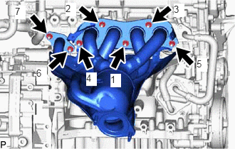
Using a 12 mm deep socket wrench, temporarily install the exhaust manifold to the cylinder head sub-assembly with 7 new nuts.
Using the 12 mm deep socket wrench, tighten the 7 nuts in the order shown in the illustration.
- Torque:
- 26 N*m (265 kgf*cm, 19 ft.*lbf)
17118
3.INSTALL MANIFOLD STAY
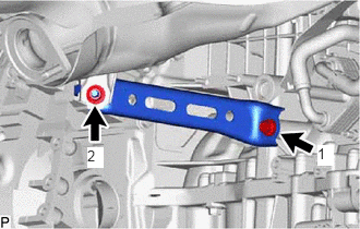
Temporarily install the manifold stay to the exhaust manifold and cylinder block sub-assembly with the bolt and nut.
Tighten the bolt and nut in the order shown in the illustration.
- Torque:
- 43 N*m (438 kgf*cm, 32 ft.*lbf)
58151
4.INSTALL NO. 1 UPPER FRONT FLOOR HEAT INSULATOR
Install the No. 1 upper front heat insulator to the vehicle body with the 2 nuts.
- Torque:
- 4.9 N*m (50 kgf*cm, 43 in.*lbf)
17167
5.INSTALL NO. 1 EXHAUST MANIFOLD HEAT INSULATOR
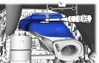
| *a | Torque Wrench Fulcrum Length |
Using a 10 mm union nut wrench, install the No. 1 exhaust manifold heat insulator to the exhaust manifold with the 3 bolts.
- Torque:
- Specified tightening torque : 10 N*m (102 kgf*cm, 7 ft.*lbf)
- HINT:
- ·
Calculate the torque wrench reading when changing the fulcrum length of the torque wrench.
·When using a 10 mm union nut wrench (fulcrum length of 22 mm (0.866 in.)) + torque wrench (fulcrum length of 162 mm (6.38 in.)): 8.8 N*m (90 kgf*cm, 78 in.*lbf)
25706
6.INSTALL NO. 1 VACUUM TRANSMITTING PIPE SUB-ASSEMBLY
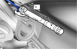
| *a | Torque Wrench Fulcrum Length |
Using a 14 mm union nut wrench, install the No. 1 vacuum transmitting pipe sub-assembly to the exhaust manifold.
- Torque:
- Specified tightening torque : 30 N*m (306 kgf*cm, 22 ft.*lbf)
- HINT:
- ·
Calculate the torque wrench reading when changing the fulcrum length of the torque wrench.
·When using a 10 mm union nut wrench (fulcrum length of 22 mm (0.866 in.)) + torque wrench (fulcrum length of 180 mm (7.09 in.)): 26.3 N*m (268 kgf*cm, 19 ft.*lbf)
Install the nut and connect the No. 1 vacuum transmitting pipe sub-assembly to the exhaust manifold.
- Torque:
- 10 N*m (102 kgf*cm, 7 ft.*lbf)
25760
7.INSTALL VACUUM TRANSMITTING HOSE ASSEMBLY
Connect the vacuum transmitting hose assembly to the No. 1 tube and slide the clip to secure it.
8.INSTALL WIRE HARNESS CLAMP BRACKET
Install the wire harness clamp bracket with the bolt.
- Torque:
- 13 N*m (133 kgf*cm, 10 ft.*lbf)
89467B
9.INSTALL AIR FUEL RATIO SENSOR (for Sensor 1)
17410
10.INSTALL FRONT EXHAUST PIPE ASSEMBLY
Install 2 new gaskets to the front exhaust pipe assembly.
Connect the front exhaust pipe assembly to the 2 exhaust pipe supports.
Install the front exhaust pipe assembly to the exhaust manifold and tail exhaust pipe assembly with 2 new bolts and 2 new nuts.
- Torque:
- 43 N*m (438 kgf*cm, 32 ft.*lbf)
Connect the No. 2 exhaust gas temperature sensor connector.
Attach the 4 clamps.
Connect the exhaust gas temperature sensor connector.
Attach the 2 clamps.
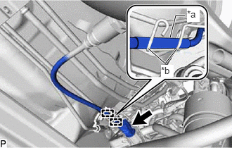
| *a | White Heat Shrinking Tube |
| *b | Wire Harness Clamp |
Connect the air fuel ratio sensor (for Sensor 2) connector.
Attach the 2 wire harness clamps so that the white heat shrinking tube is positioned as shown in the illustration.
11.INSPECT FOR EXHAUST GAS LEAK
51420
12.INSTALL NO. 2 ENGINE UNDER COVER ASSEMBLY
13. RESET TOTAL SHORT TRIP ESTIMATE
- HINT:
-
This function is used for initializing the value of "Total Short Trip Estimate Bank 1" which was stored to the ECM when replacing the TWC (front catalyst).