K121 CVT VALVE BODY ASSEMBLY INSTALLATION
CAUTION / NOTICE / HINT
- HINT:
-
Shift shock may increase after replacing the transmission valve body assembly. In this case, shift shock will reduce as the vehicle in driven.
PROCEDURE

 35410J
1.INSTALL TRANSMISSION VALVE BODY ASSEMBLY
35410J
1.INSTALL TRANSMISSION VALVE BODY ASSEMBLY
Coat 4 new transaxle case gaskets with Toyota Genuine CVT fluid FE and install them to the transaxle case sub-assembly.
Coat a new front oil pump cover gasket with Toyota Genuine CVT fluid FE and install it to the transaxle case sub-assembly.
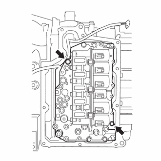
Temporarily install the transmission valve body assembly to the transaxle case sub-assembly with the 2 bolts.
- Bolt Length:
40 mm (1.57 in.)
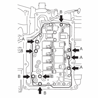
Temporarily install the 9 bolts.
- Bolt Length:
Bolt (A) Bolt (B) 40 mm (1.57 in.) 55 mm (2.17 in.)
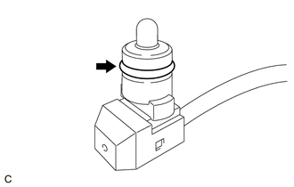
Coat a new O-ring with Toyota Genuine CVT fluid FE and install it to the temperature sensor.
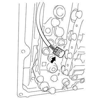
Connect the temperature sensor to the transmission valve body assembly.
- NOTICE:
-
To prevent it from being pinched between the transmission valve body assembly and the transaxle side cover sub-assembly, do not let the transmission wire ride up over the area shown in the illustration.
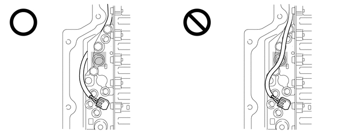 0,0 0,0 false
Do not let transmission wire protrude into this area. - -
Temporarily install the temperature sensor clamp to the transmission valve body assembly with the bolt.
- Bolt Length:
55 mm (2.17 in.)
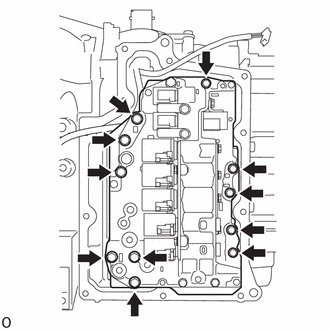
Tighten the 11 bolts.
- Torque:
- 10.8 N*m (110 kgf*cm, 8 ft.*lbf)
Connect the 8 solenoid valve connectors.
Attach the clamp to connect the transmission wire to the solenoid lock plate.
35015Y
2.INSTALL TRANSAXLE SIDE COVER SUB-ASSEMBLY
3.CHECK CONTINUOUSLY VARIABLE TRANSAXLE SYSTEM
- NOTICE:
-
If continuously variable transaxle parts have been replaced, refer to Parts Replacement Compensation Table to determine if any additional operations are necessary.