K121 CVT SHIFT LEVER INSPECTION
PROCEDURE

 1.INSPECT SHIFT LOCK CONTROL ECU (w/ Smart Entry and Start System)
- HINT:
-
If the results of the following inspections are as specified but a malfunction has occurred, replace the shift lock control unit assembly.
Inspect wire harness:
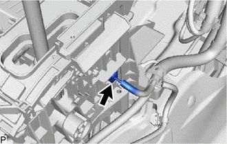
Disconnect the shift lock control ECU connector.
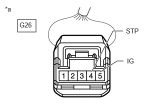
| *a | Front view of wire harness connector
(to Shift Lock Control ECU) |
Measure the voltage according to the value(s) in the table below.
- Standard Voltage:
Tester Connection Condition Specified Condition G26-4 (STP) - Body ground Brake pedal depressed 11 to 14 V Brake pedal released Below 1 V G26-5 (IG) - Body ground Ignition switch ON 11 to 14 V Ignition switch off Below 1 V
If the result is not as specified, repair or replace the shift lock control ECU wire harness.
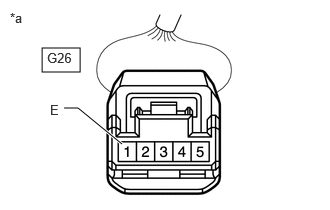
| *a | Front view of wire harness connector
(to Shift Lock Control ECU) |
Measure the resistance according to the value(s) in the table below.
- Standard Resistance:
Tester Connection Condition Specified Condition G26-1 (E) - Body ground Always Below 1 Ω
If the result is not as specified, repair or replace the shift lock control ECU wire harness.
Inspect shift lock solenoid:
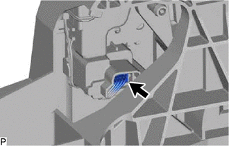
Disconnect the shift lock solenoid connector.

| *a | Front view of wire harness connector
(to Shift Lock Solenoid) |
Measure the resistance according to the value(s) in the table below.
- Standard Resistance:
Tester Connection Condition Specified Condition 4 (P) - 3 (E2) Shift lever in P 10 kΩ or higher Shift lever not in P Below 1 Ω
If the result is not as specified, replace the shift lock control unit assembly.
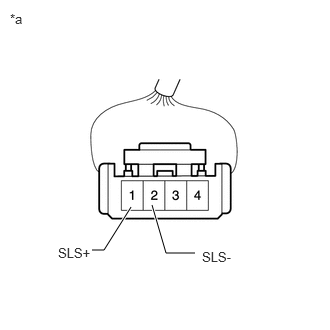
| *a | Front view of wire harness connector
(to Shift Lock Solenoid) |
Measure the resistance according to the value(s) in the table below.
- Standard Resistance:
Tester Connection Condition Specified Condition 1 (SLS+) - 2 (SLS-) Always 112 Ω
If the result is not as specified, replace the shift lock control unit assembly.
2.INSPECT SHIFT LOCK CONTROL ECU (w/o Smart Entry and Start System)
- HINT:
-
If the results of the following inspections are as specified but a malfunction has occurred, replace the shift lock control unit assembly.
Inspect wire harness:
Disconnect the shift lock control ECU connector.

| *a | Front view of wire harness connector
(to Shift Lock Control ECU) |
Measure the voltage according to the value(s) in the table below.
- Standard Voltage:
Tester Connection Condition Specified Condition G27-8 (STP) - Body ground Brake pedal depressed 11 to 14 V Brake pedal released Below 1 V G27-1 (ACC) - Body ground Ignition switch ACC 11 to 14 V Ignition switch off Below 1 V G27-4 (IG) - Body ground Ignition switch ON 11 to 14 V Ignition switch off Below 1 V
If the result is not as specified, repair or replace the shift lock control ECU wire harness.
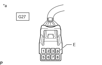
| *a | Front view of wire harness connector
(to Shift Lock Control ECU) |
Measure the resistance according to the value(s) in the table below.
- Standard Resistance:
Tester Connection Condition Specified Condition G27-7 (E) - Body ground Always Below 1 Ω
If the result is not as specified, repair or replace the shift lock control ECU wire harness.
Inspect key interlock solenoid operation signal:
Connect the shift lock control ECU connector.
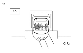
| *a | Component with harness connected
(Shift Lock Control ECU) |
Measure the voltage according to the value(s) in the table below.
- Standard Voltage:
Tester Connection Condition Specified Condition G27-5 (KLS+) - Body ground Ignition switch ACC and shift lever in P Below 1 V Ignition switch ACC and shift lever not in P 11 to 14 V
- HINT:
-
Do not disconnect the shift lock control ECU connector.
If the result is not as specified, replace the shift lock control unit assembly.
Inspect shift lock solenoid:
Disconnect the shift lock solenoid connector.
| *a | Front view of wire harness connector
(to Shift Lock Solenoid) |
Measure the resistance according to the value(s) in the table below.
- Standard Resistance:
Tester Connection Condition Specified Condition 4 (P) - 3 (E2) Shift lever in P 10 kΩ or higher Shift lever not in P Below 1 Ω
If the result is not as specified, replace the shift lock control unit assembly.
| *a | Front view of wire harness connector
(to Shift Lock Solenoid) |
Measure the resistance according to the value(s) in the table below.
- Standard Resistance:
Tester Connection Condition Specified Condition 1 (SLS+) - 2 (SLS-) Always 112 Ω
If the result is not as specified, replace the shift lock control unit assembly.
3.INSPECT TRANSMISSION CONTROL SWITCH
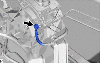
Disconnect the transmission control switch connector.
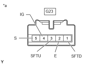
| *a | Component without harness connected
(Transmission Control Switch (Transmission Floor Shift Assembly)) |
Measure the resistance according to the value(s) in the table below.
- Standard Resistance:
Tester Connection Condition Specified Condition G23-4 (IG) - G23-5 (S) Shift lever in M, "+" or "-" Below 1 Ω Shift lever not in M, "+" or "-" 10 kΩ or higher G23-3 (SFTU) - G23-2 (E) Shift lever held in "+"
(Up-shift)Below 1 Ω Shift lever not held in "+"
(Up-shift)10 kΩ or higher G23-1 (SFTD) - G23-2 (E) Shift lever held in "-"
(Down-shift)Below 1 Ω Shift lever not held in "-"
(Down-shift)10 kΩ or higher
If the result is not as specified, replace the shift lock control unit assembly.