RM36D0EC
_52
Drivetrain
_138176
K121 CVT
_0579401
REVOLUTION SENSOR(NSS SENSOR)
G
K121 CVT REVOLUTION SENSOR(NSS SENSOR) INSPECTION
PROCEDURE

 89413T
1.INSPECT TRANSMISSION REVOLUTION SENSOR (NSS)
89413T
1.INSPECT TRANSMISSION REVOLUTION SENSOR (NSS)
a.
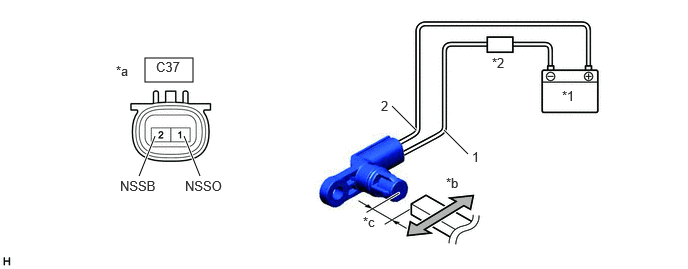
Connect the battery to the transmission revolution sensor (NSS) as shown in the illustration.
1.51,0.604 2.01,0.854
0.5,0.25
1.448,1.833 1.615,1.417
true
2.083,1.833 1.917,1.417
true
4.083,1.104 4.333,1.354
true
4.625,1.354 4.875,1.604
true
5.854,0.917 6.167,1.073
0.313,0.156
10
false
*1
5.125,0.573 5.438,0.729
0.313,0.156
10
false
*2
1.208,0.656 1.521,0.813
0.313,0.156
10
false
*a
4.646,1.823 4.958,1.979
0.313,0.156
10
false
*b
3.781,2.229 4.094,2.385
0.313,0.156
10
false
*c
1.25,1.854 1.708,2.052
0.458,0.198
10
false
NSSB
1.927,1.854 2.385,2.052
0.458,0.198
10
false
NSSO
3.969,1.021 4.125,1.219
0.156,0.198
10
false
2
4.917,1.552 5.073,1.75
0.156,0.198
10
false
1
1.625,0.615 2.083,0.813
0.458,0.198
10
false
C37
| *1 | Battery | *2 | Ammeter |
| *a | Component without harness connected
(Transmission Revolution Sensor (NSS)) |
*b | Magnet |
| *c | 5 mm (0.197 in.) or less | - | - |
b.
Wave a magnet left and right 5 mm (0.197 in.) or less from the tip of the transmission revolution sensor (NSS) to output a high/low signal while measuring the current.
- NOTICE:
-
Make sure to wave the magnet during the inspection. The current will not change unless the magnet is moved as shown in the illustration.
c.
Measure the current according to the value(s) in the table below.
- Standard Current:
Tester Connection Condition Specified Condition C37-1 (NSSO) - C37-2 (NSSB) Low signal 4 to 8 mA High signal 12 to 16 mA
If the result is not as specified, replace the transmission revolution sensor (NSS).