REAR SUSPENSION REAR STABILIZER BAR INSTALLATION
PROCEDURE

 48818
1.INSTALL REAR STABILIZER BUSHING
48818
1.INSTALL REAR STABILIZER BUSHING
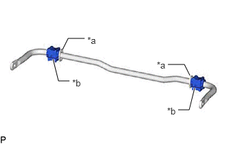
| *a | Stopper |
| *b | Cutout |
Install the 2 rear stabilizer bushings to the outside of the stoppers on the rear stabilizer bar.
- NOTICE:
-
Be sure to install the rear stabilizer bushings so that each cutout faces the front of the vehicle.
- HINT:
-
The cutout of the rear stabilizer bushing can be positioned either up or down.
48832A
2.INSTALL REAR NO. 1 STABILIZER BAR BRACKET LH
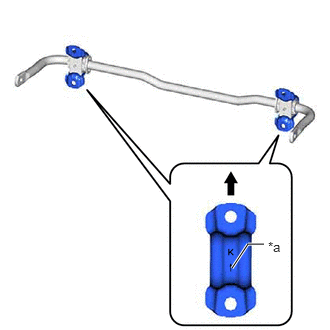
| *a | Arrow Mark |

|
Upper of the Vehicle |
Install the rear No. 1 stabilizer bar bracket LH to the rear stabilizer bushing.
- NOTICE:
-
Be sure to install the rear No. 1 stabilizer bar bracket LH so that each arrow mark faces the upper of the vehicle.
48832A
3.INSTALL REAR NO. 1 STABILIZER BAR BRACKET RH
- HINT:
-
Perform the same procedure as for the LH side.
48835
4.INSTALL REAR LOWER STABILIZER BRACKET
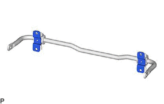
Install the 2 rear lower stabilizer brackets to the rear stabilizer bushing.
48812
5.INSTALL REAR STABILIZER BAR
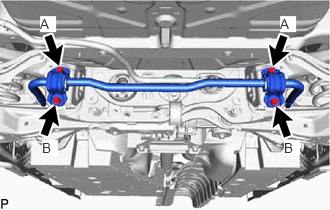
Install the rear stabilizer bar, rear No. 1 stabilizer bar bracket LH, rear No. 1 stabilizer bar bracket RH, rear No. 2 stabilizer bar bracket LH, rear No. 2 stabilizer bar bracket RH and 2 rear stabilizer bushings to the rear suspension member sub-assembly with the 4 bolts.
- Torque:
- 78 N*m (795 kgf*cm, 58 ft.*lbf)
- NOTICE:
-
Temporarily tighten the bolt (A) and then fully tighten the 2 bolts in the order of (B) and (A).
6.STABILIZE SUSPENSION
48840A
7.INSTALL REAR STABILIZER LINK ASSEMBLY LH
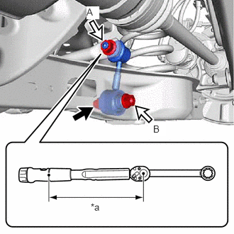
| *a | Torque Wrench Fulcrum Length |
Using a ball joint lock nut wrench, install the rear stabilizer link assembly LH with the nut (A).
- Torque:
- 100 N*m (1020 kgf*cm, 74 ft.*lbf)
- HINT:
- ·
If the ball joint turns together with the nut, use a 6 mm hexagon socket wrench to hold the stud bolt.
·Calculate the torque wrench reading when changing the fulcrum length of the torque wrench.
·When using a ball joint lock nut wrench (fulcrum length of 159 mm (6.260 in.)) + torque wrench (fulcrum length of 400 mm (15.748 in.)):
71.6 N*m (730 kgf*cm, 53 ft.*lbf)
Install the rear stabilizer link assembly LH with the bolt and nut (B).
- Torque:
- 81 N*m (826 kgf*cm, 60 ft.*lbf)
- NOTICE:
-
Because the nut has its own stopper, do not turn the nut. Tighten the bolt with the nut secured.
48830D
8.INSTALL REAR STABILIZER LINK ASSEMBLY RH
- HINT:
-
Perform the same procedure as for the LH side.
58399D
9.INSTALL NO. 2 FLOOR UNDER COVER (for Gasoline Model)
58398F
10.INSTALL NO. 1 FLOOR UNDER COVER (for Gasoline Model)
58166A
11.INSTALL FRONT FLOOR COVER LH (for Gasoline Model)
58166A
12.INSTALL FRONT FLOOR COVER RH (for Gasoline Model)
51420
13.INSTALL NO. 2 ENGINE UNDER COVER ASSEMBLY (for Gasoline Model)
51441
14.INSTALL NO. 1 ENGINE UNDER COVER (for Gasoline Model)
53896B
15.INSTALL FRONT FENDER FRONT SPLASH SHIELD LH (for Gasoline Model)
53895B
16.INSTALL FRONT FENDER FRONT SPLASH SHIELD RH (for Gasoline Model)
58327B
17.INSTALL MAIN MUFFLER HEAT INSULATOR
Install the main muffler heat insulator to the vehicle body with the 4 nuts.
- Torque:
- 4.9 N*m (50 kgf*cm, 43 in.*lbf)
17430
18.INSTALL TAIL EXHAUST PIPE ASSEMBLY
for A25F-FXS [Production Date from 2021/08]:
19.INSTALL REAR WHEEL
20.INSPECT FOR EXHAUST GAS LEAK
for A25F-FXS [Production Date from 2021/08]: