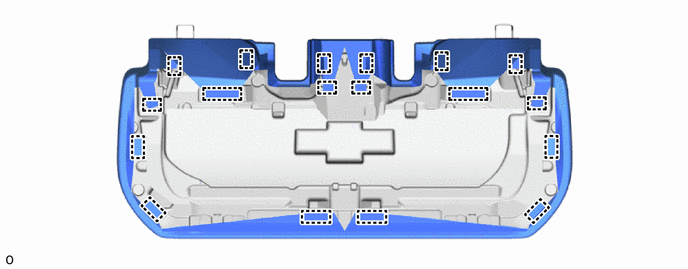
SEAT REAR SEAT ASSEMBLY(for GTMC Made) REASSEMBLY
CAUTION / NOTICE / HINT
- CAUTION:
- ·
Wear protective gloves. Sharp areas on the parts may injure your hands.
·There is risk of injury.
PROCEDURE

 72057
1.INSTALL REAR SEAT LOCK CONTROL LEVER SUB-ASSEMBLY RH
72057
1.INSTALL REAR SEAT LOCK CONTROL LEVER SUB-ASSEMBLY RH
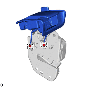
Attach the hook and install the rear seat lock control lever sub-assembly RH to the rear seatback lock assembly RH.
72630C
2.INSTALL REAR SEATBACK LOCK ASSEMBLY RH
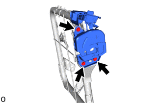
Install the rear seatback lock assembly RH with the 3 bolts.
- Torque:
- 30 N*m (306 kgf*cm, 22 ft.*lbf)
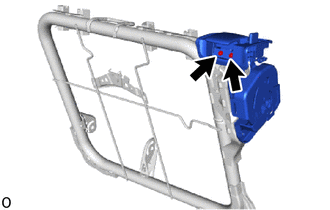
Install the 2 screws.
73350C
3.INSTALL REAR CENTER SEAT OUTER BELT ASSEMBLY
71077S
4.INSTALL SEPARATE TYPE REAR SEATBACK COVER RH
- HINT:
-
When installing a separate type rear seatback cover RH, refer to Precaution in order to prevent wrinkles from forming.
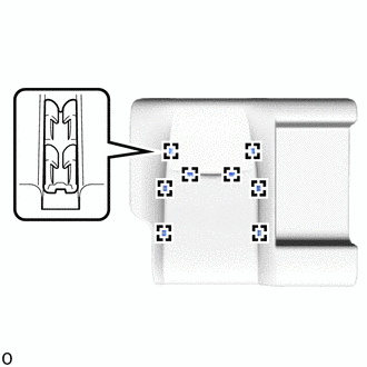
Attach the hook to install the separate type rear seatback cover RH to the separate type rear seatback pad RH.
- NOTICE:
-
Be careful not to dirty or damage the separate type rear seatback cover RH.
5.INSTALL SEPARATE TYPE REAR SEATBACK COVER WITH PAD
Set the separate type rear seatback cover with pad to the rear seatback frame sub-assembly RH.
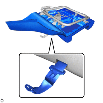
Pass the rear center seat outer belt assembly through the hole of separate type rear seatback cover with pad.
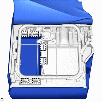
Attach the hook.
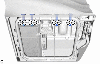
Attach the claw and install the 4 rear seat headrest supports.
72806B
6.INSTALL REAR CENTER SEAT ARMREST CUP HOLDER SUB-ASSEMBLY
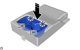

|
Install in this Direction |
Attach the guide and claw and install the rear center seat armrest cup holder sub-assembly as shown in the illustration.
72830
7.INSTALL REAR CENTER SEAT ARMREST ASSEMBLY
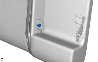
Install the bush.
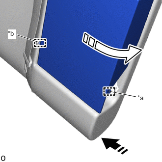
| *a | Outside Location Pin |
| *b | Inside Location Pin |
|
|
Install in this Direction (1) |

|
Install in this Direction (2) |
Attach the inside location pin in the installation direction (1) shown in the illustration.
Attach the outside location pin in the installation direction (2) shown in the illustration.
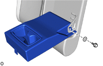
| *a | Washer |
Fold the rear center seat armrest assembly forward.
Install the rear center seat armrest assembly with the washer and bolt.
- Torque:
- 21 N*m (214 kgf*cm, 15 ft.*lbf)
72868
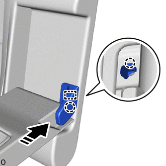
8.INSTALL CENTER ARMREST HINGE COVER RH
|
|
Install in this Direction |
Attach the guide and claw and install the center armrest hinge cover RH.
71701C
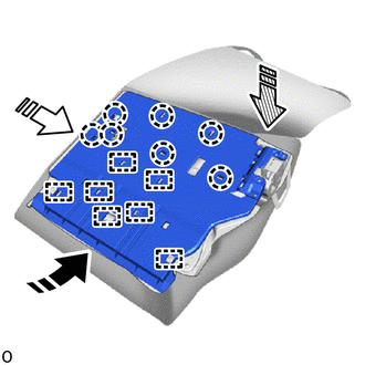
9.INSTALL REAR SEATBACK BOARD SUB-ASSEMBLY RH
| *a | Guide |
| *b | Hook |
|
|
Install in this Direction (1) |
|
|
Install in this Direction (2) |

|
Install in this Direction (3) |
Attach the hook in the installation direction (1) shown in the illustration.
Attach the guide in the installation direction (2) shown in the illustration.
Attach the claw in the installation direction (3) shown in the illustration.
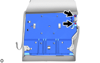
Install the rear seatback board sub-assembly RH with the 2 clips.
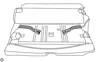
Close the 2 fasteners.
Put the 2 fasteners in the hole of rear seatback board sub-assembly RH.
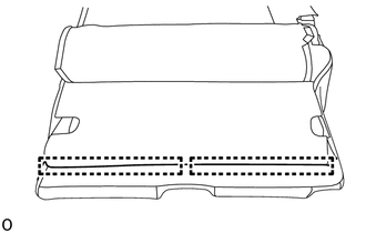
Attach the hook.
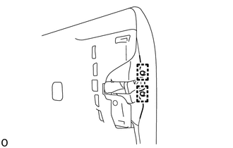
Attach the hook.
72667A
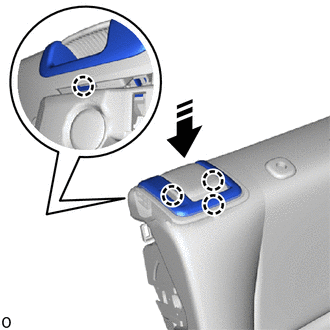
10.INSTALL REAR UPPER SEATBACK LOCK BEZEL RH
|
|
Install in this Direction |
Attach the claw and install the rear upper seatback lock bezel RH.
72668E
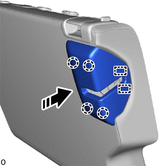
11.INSTALL REAR LOWER SEATBACK LOCK BEZEL RH
|
|
Install in this Direction |
Attach the guide and claw and install the rear lower seatback lock bezel RH.
73178A
12.INSTALL SEAT BELT ANCHOR COVER CAP
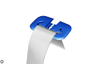
Pass the rear center seat outer belt assembly from the slit of rear seat shoulder belt cover.
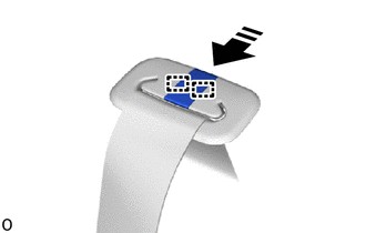
|
|
Install in this Direction |
Attach the guide and install the seat belt anchor cover cap as shown in the illustration.
73373
13.INSTALL REAR SEAT SHOULDER BELT COVER
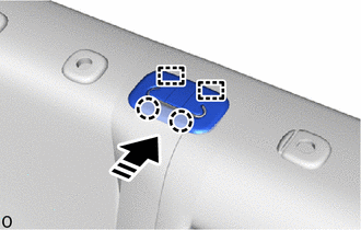
|
|
Install in this Direction |
Attach the guide and claw and install the rear seat shoulder belt cover.
72058A
14.INSTALL REAR SEAT LOCK CONTROL LEVER SUB-ASSEMBLY LH
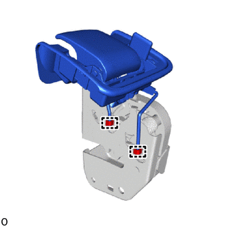
Attach the hook and install the rear seat lock control lever sub-assembly LH to the rear seatback lock assembly LH.
72640A
15.INSTALL REAR SEATBACK LOCK ASSEMBLY LH
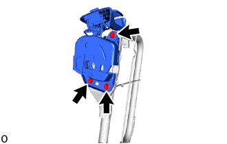
Install the rear seatback lock assembly LH with the 3 bolts.
- Torque:
- 30 N*m (306 kgf*cm, 22 ft.*lbf)
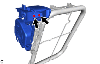
Install the 2 screws.
71078S
16.INSTALL SEPARATE TYPE REAR SEATBACK COVER LH
- HINT:
-
When installing a separate type rear seatback cover LH, refer to Precaution in order to prevent wrinkles from forming.
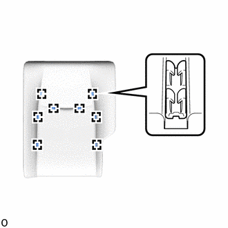
Attach the hook and install the separate type rear seatback cover LH to the separate type rear seatback pad LH.
- NOTICE:
-
Be careful not to dirty or damage the separate type rear seatback cover LH.
17.INSTALL SEPARATE TYPE REAR SEATBACK COVER WITH PAD
Set the separate type rear seatback cover with pad to the rear seatback frame sub-assembly LH.
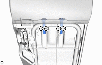
Attach the claw and install the 2 rear seat headrest supports.
71702C
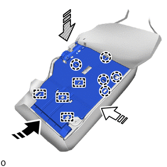
18.INSTALL REAR SEATBACK BOARD SUB-ASSEMBLY LH
| *a | Guide |
| *b | Hook |
|
|
Install in this Direction (1) |
|
|
Install in this Direction (2) |
|
|
Install in this Direction (3) |
Attach the hook in the installation direction (1) shown in the illustration.
Attach the guide in the installation direction (2) shown in the illustration.
Attach the claw in the installation direction (3) shown in the illustration.
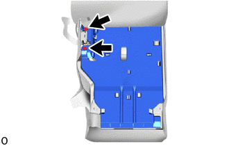
Install the rear seatback board sub-assembly LH with the 2 clips.
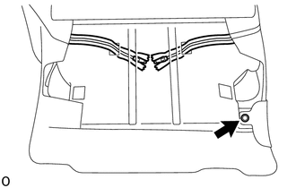
Install the clip.
Close the 2 fasteners.
Put the 2 fasteners in the hole of rear seatback board sub-assembly LH.
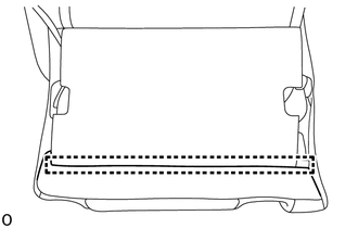
Attach the hook.
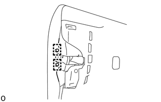
Attach the hook.
72667B
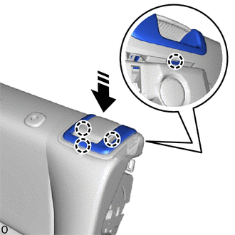
19.INSTALL REAR UPPER SEATBACK LOCK BEZEL LH
|
|
Install in this Direction |
Attach the claw and install the rear upper seatback lock bezel LH.
72668F
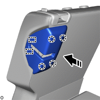
20.INSTALL REAR LOWER SEATBACK LOCK BEZEL LH
|
|
Install in this Direction |
Attach the guide and claw and install the rear lower seatback lock bezel LH.
71075B
21.INSTALL BENCH TYPE REAR SEAT CUSHION COVER
- HINT:
-
When installing a bench type rear seat cushion cover, refer to Precaution in order to prevent wrinkles from forming.
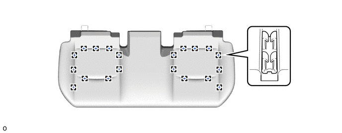
Attach the hook and install the bench type rear seat cushion cover to the rear seat cushion pad.
- NOTICE:
-
Be careful not to dirty or damage the bench type rear seat cushion cover.
Attach the hook.
for Gasoline Model:
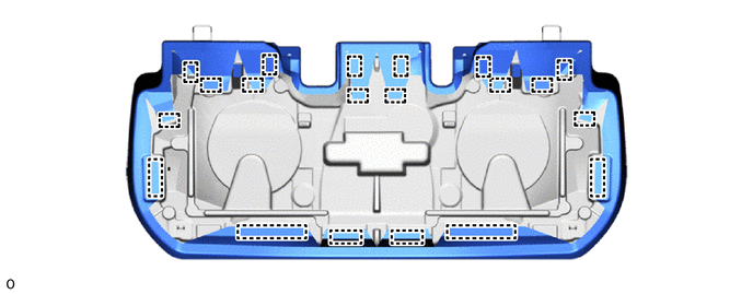
for HV Model: