M20C-FKS EMISSION CONTROL EMISSION CONTROL SYSTEM ON-VEHICLE INSPECTION
CAUTION / NOTICE / HINT
- CAUTION:
-
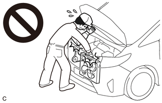
- ·
When working near the engine room while the engine has started or the power source mode is ignition switch to ON (IG), do not touch the fan and generator V belt or rotating components such as the fan, etc.
·Touching the fan and generator V belt or rotating components such as the fan, etc. could result in your hand or clothing getting caught and pulled in.
PROCEDURE

 1.INSPECT FUEL CUT OPERATION
- CAUTION:
- ·
When working near the engine room while the engine has started or the power source mode is ignition switch to ON (IG), do not touch the fan and generator V belt or rotating components such as the fan, etc.
·Touching the fan and generator V belt or rotating components such as the fan, etc. could result in your hand or clothing getting caught and pulled in.
Start the engine.
Warm up the engine.
Increase the engine speed to approximately 3500 rpm.
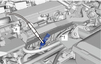
| *1 | Fuel Injector Assembly |
| *a | Sound Scope |
Use a sound scope to check for fuel injector assembly operating sounds.
When the accelerator pedal is fully released, check that fuel injector assembly operating sounds stop momentarily and then resume.
- Standard:
Item Specified Condition Fuel cut permission engine speed 2500 rpm or higher Fuel injection restart engine speed 1400 rpm
If the result is not as specified, check the fuel injector assemblies, wire harness and ECM.
2.VISUALLY CHECK HOSES, CONNECTIONS AND GASKETS
Visually check that the hoses, connections and gaskets have no cracks, leaks or damage.
- NOTICE:
- ·
Detachment or other problems with the engine oil level dipstick, oil filler cap sub-assembly, ventilation hose or other components may cause the engine to run improperly.
·Air suction caused by disconnections, looseness or cracks in any part of the air induction system between the throttle body with motor assembly and cylinder head sub-assembly will cause engine failure or engine malfunctions.
If any defects are found, replace parts as necessary.
3.INSPECT EVAPORATIVE EMISSION CONTROL SYSTEM
- CAUTION:
- ·
When working near the engine room while the engine has started or the power source mode is ignition switch to ON (IG), do not touch the fan and generator V belt or rotating components such as the fan, etc.
·Touching the fan and generator V belt or rotating components such as the fan, etc. could result in your hand or clothing getting caught and pulled in.
Connect the GTS to the DLC3.
Start the engine.
Warm up the engine.
Turn the GTS on.
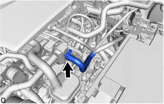
Slide the clip and disconnect the No. 1 fuel vapor feed hose from the purge valve (purge VSV).
Enter the following menus: Powertrain / Engine / Active Test / Activate the EVAP Purge VSV.
- Powertrain > Engine > Active Test
-
Tester Display Activate the EVAP Purge VSV - 50004 372 1
Check that vacuum occurs at the purge valve (purge VSV) port.
If vacuum does not occur, check the following items.
Purge valve (purge VSV)
Clogging in the No. 2 fuel vapor feed hose that connects the intake manifold and purge valve (purge VSV)
Exit Active Test mode and connect the No. 1 fuel vapor feed hose assembly to the purge valve (purge VSV) and slide the clip to secure it.
If the result is not as specified, replace the purge valve (purge VSV), wire harness or ECM.
Enter the following menus: Powertrain / Engine / Data List / EVAP (Purge) VSV.
- Powertrain > Engine > Data List
-
Tester Display EVAP (Purge) VSV - 50003 372 226
Warm up the engine and drive the vehicle.
Confirm that the purge valve (purge VSV) opens.
If the result is not as specified, replace the purge valve (purge VSV), wire harness or ECM.
4.CHECK FUEL TANK AND VENT LINE
Disconnect the fuel tank vent hose from the canister (charcoal canister assembly).
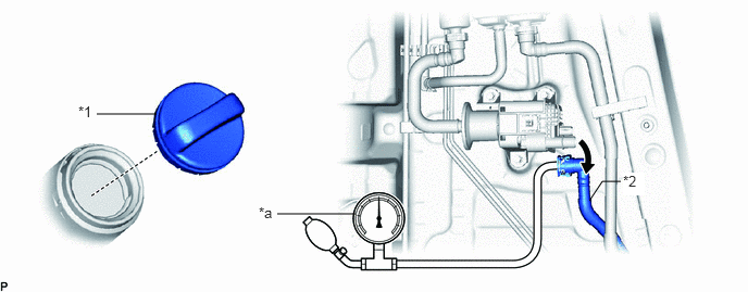
| *1 | Fuel Tank Cap Assembly | *2 | Fuel Tank Vent Hose |
| *a | Pressure Gauge | - | - |
Connect a pressure gauge to the fuel tank vent hose.
Apply 4 kPa (0.04 kgf/cm2, 0.6 psi) of pressure to the vent line of the fuel tank assembly.
- HINT:
-
Perform this inspection with the fuel tank assembly less than 90% full. When the fuel tank assembly is full, the fuel fill check valve closes and the pressure is released through the 2 mm (0.0787 in.) orifice. As a result, when the fuel tank cap assembly is removed, the pressure does not decrease smoothly.
Check that the fuel tank assembly pressure is maintained for some time and does not decrease immediately.
- HINT:
-
If the pressure decreases immediately, one of the following may apply:
- ·
The fuel tank cap assembly is not completely tightened.
·The fuel tank cap assembly is damaged.
·Air is leaking from the vent line.
·The fuel tank assembly is damaged.
Remove the fuel tank cap assembly and check that the pressure is released smoothly.
If the pressure is not released smoothly, replace the fuel tank assembly.
Reconnect the fuel tank vent hose to the canister (charcoal canister assembly).
5.INSPECT AIR LINE
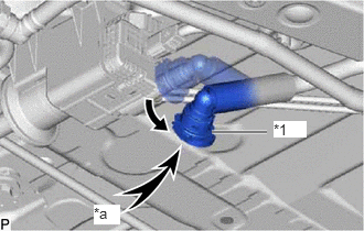
| *1 | Fuel Tank Vent Hose |
| *a | Air |
Disconnect the fuel tank vent hose from the leak detection pump sub-assembly.
Check that air flows freely into the air line.
If air does not flow freely into the air line, repair or replace the fuel tank vent hose.
Connect the fuel tank vent hose to the leak detection pump sub-assembly.