HEATING / AIR CONDITIONING AIR CONDITIONING UNIT(for M20C-FKS) REASSEMBLY
PROCEDURE

 87114B
1.INSTALL HEATER COVER
87114B
1.INSTALL HEATER COVER
- NOTICE:
- Perform this procedure only when removal/installation of the heater cover is necessary.
-
If the heater cover is removed, the heater cover itself can be reused, but the air conditioning radiator assembly cannot be reused. After the heater cover is installed, the support (triangular rib) on the air conditioning radiator assembly is crushed. Therefore, if the air conditioning radiator assembly is reused, abnormal noise may occur due to looseness.

|
Install in this Direction |
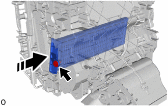
Install the heater cover to a new lower heater case as shown in the illustration.
Install the screw.
88625
2.INSTALL NO. 1 COOLER THERMISTOR
88501
3.INSTALL NO. 1 COOLER EVAPORATOR SUB-ASSEMBLY
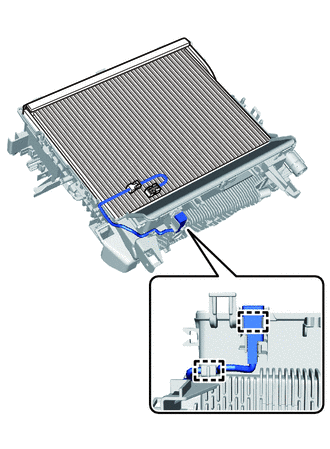
Install the No. 1 cooler evaporator sub-assembly with No. 1 cooler thermistor to the upper heater case.
Attach the guide.
While inserting the No. 1 cooler thermistor into the guide, attach the guide and claw as shown in the illustration.
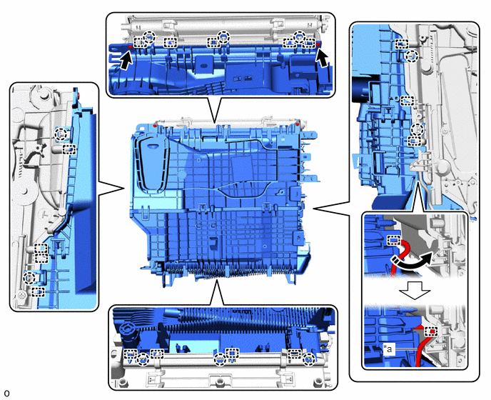
| *a | No. 1 Cooler Thermistor Lead Wire | - | - |
|
|
Secure the lead wire between the guide | - | - |
Install the upper heater case with No. 1 cooler evaporator sub-assembly to the lower heater case with the 2 screws.
88515
4.INSTALL COOLER EXPANSION VALVE
Remove the vinyl tape from the No. 1 cooler evaporator sub-assembly and cooler expansion valve.
Sufficiently apply compressor oil to 2 new O-rings and the fitting surfaces of the No. 1 cooler evaporator sub-assembly.
- Compressor Oil:
ND-OIL 8 or equivalent
Install the 2 O-rings to the No. 1 cooler evaporator sub-assembly.
- NOTICE:
-
Keep the O-rings and O-ring fitting surfaces free of foreign matter.
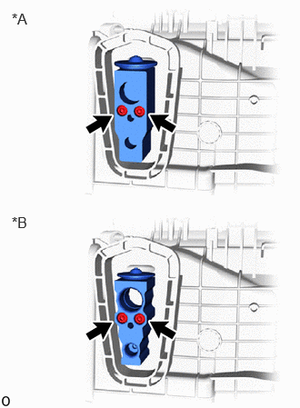
| *A | for Automatic Air Conditioning System |
| *B | for Manual Air Conditioning System |
Using a 4 mm hexagon socket wrench, install the cooler expansion valve with the 2 hexagon bolts.
- Torque:
- 3.5 N*m (36 kgf*cm, 31 in.*lbf)
- NOTICE:
-
Make sure not to cut the O-ring while installing it. (Cut O-rings cannot be installed)
88899L
5.INSTALL COOLING UNIT PARTS
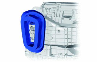
Install the cooling unit parts.
87107A
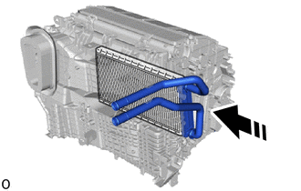
6.INSTALL HEATER RADIATOR UNIT SUB-ASSEMBLY
|
|
Install in this Direction |
Install the heater radiator unit sub-assembly as shown in the illustration.
87124B
7.INSTALL HEATER CLAMP
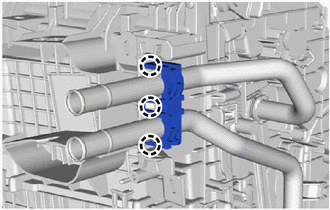
Attach the claw to install the heater clamp.
88897M
8.INSTALL HEATER PIPE GROMMET
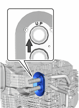
Install the heater pipe grommet as shown in the illustration.
- NOTICE:
-
Install the heater pipe grommet with the arrow facing up.
87050D
9.INSTALL NO. 2 AIR CONDITIONING RADIATOR DAMPER SERVO SUB-ASSEMBLY
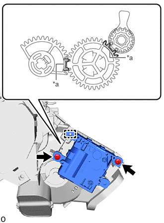
| *a | Gear Alignment Part |
Align the gear alignment part of the heater case with the gear alignment part of the No. 2 air conditioning radiator damper servo sub-assembly as shown in the illustration.
Attach the guide.
Install the No. 2 air conditioning radiator damper servo sub-assembly with the 2 screws.
87050C
10.INSTALL NO. 1 AIR CONDITIONING RADIATOR DAMPER SERVO SUB-ASSEMBLY
for Automatic Air Conditioning System:
Align the fitting part and gear alignment part of the heater case with the fitting part and gear alignment part of the No. 1 air conditioning radiator damper servo sub-assembly as shown in the illustration.
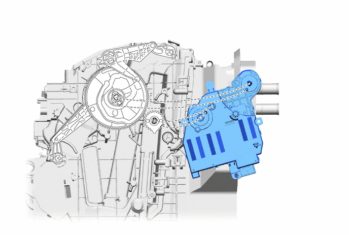
| *a | Gear Alignment Part | - | - |
for Manual Air Conditioning System:
Align the fitting part of the heater case with the fitting part of the No. 1 air conditioning radiator damper servo sub-assembly as shown in the illustration.
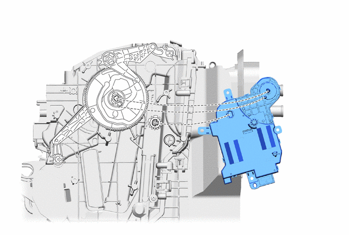
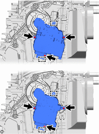
| *A | for Automatic Air Conditioning System |
| *B | for Manual Air Conditioning System |
Attach the guide.
Install the No. 1 air conditioning radiator damper servo sub-assembly with the 3 screws.
82210K
11.INSTALL AIR CONDITIONING HARNESS ASSEMBLY
Attach the clamp and guide.
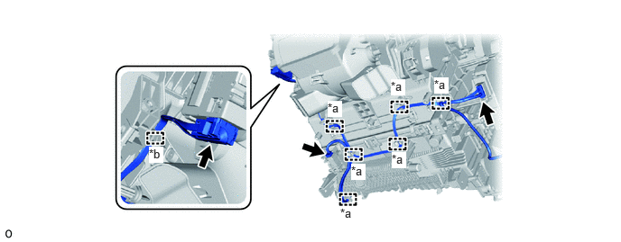
| *a | Clamp | *b | Guide |
Connect 3 connectors to install the air conditioning harness assembly.
88539J
12.INSTALL DRAIN COOLER HOSE
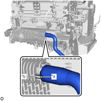
| *a | Hose Notch |
| *b | Rib |
Align the hose notch with the rib as shown in the illustration to install the drain cooler hose.
- NOTICE:
-
Do not place the rib on top of the drain cooler hose. Otherwise, water may leak into the interior.
88625Q
13.INSTALL COOLER THERMISTOR (ROOM TEMPERATURE SENSOR) (for Automatic Air Conditioning System)
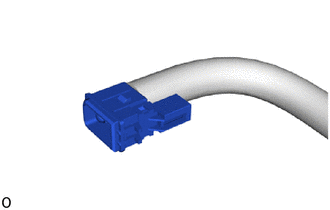
Install the cooler thermistor (room temperature sensor).
- NOTICE:
-
Securely insert it up to the base.
88897P
14.INSTALL ASPIRATOR (for Automatic Air Conditioning System)
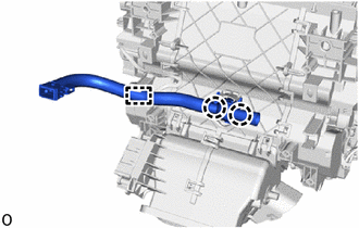
Attach the claw to install the aspirator.
- NOTICE:
-
Firmly push it down into the heater case until a "click" sound is heard.
Attach the clamp.
88326C
15.INSTALL COVER PLATE (for Manual Air Conditioning System)
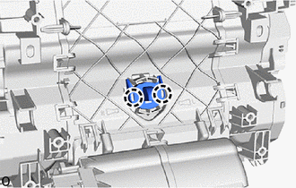
Attach the claw to install the cover plate.
- NOTICE:
-
Firmly push it down into the heater case until a "click" sound is heard.
87201B
16.INSTALL NO. 2 AIR DUCT SUB-ASSEMBLY
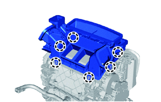
Attach the claw to install the No. 2 air duct sub-assembly.
- NOTICE:
- Firmly push it down into the heater case until a "click" sound is heard.
-
If the claws are not securely pushed in, a gap may form between the heater case and duct, and air leaking from the gap may cause abnormal noise and reduced performance. Also, the audio system may be exposed to cool air, causing it to malfunction.
87130D
17.INSTALL BLOWER ASSEMBLY