RM36D0EC
_V1
General
_083045
SPECIFICATIONS
_0403664
LIGHTING (EXT)
F
SPECIFICATIONS LIGHTING (EXT) SERVICE DATA
| Connector Condition | Tester Connection | Switch Condition | Specified Condition |
|---|---|---|---|
| Component without harness connected | 10 (A) - 12 (EL) | Light control switch AUTO position | Below 1 Ω |
| 14 (T) - 12 (EL) | Light control switch TAIL position | Below 1 Ω | |
| 5 (H) - 12 (EL) | Light control switch HEAD position | Below 1 Ω | |
| 6 (HF) - 12 (EL) | Headlight dimmer switch flash position | Below 1 Ω | |
| 1 (HU) - 12 (EL) | Headlight dimmer switch high position | Below 1 Ω | |
| 9 (TR) - 12 (EL) | Turn signal switch neutral position | 10 kΩ or higher | |
| 3 (TL) - 12 (EL) | |||
| 9 (TR) - 12 (EL) | Turn signal switch right turn position
(self cancel condition) |
Below 1 Ω | |
| 9 (TR) - 12 (EL) | Turn signal switch right turn position
(cancel ratchet operation condition) |
Below 1 Ω | |
| 9 (TR) - 11 (CR) | |||
| 11 (CR) - 12 (EL) | |||
| 3 (TL) - 12 (EL) | Turn signal switch left turn position
(self cancel condition) |
Below 1 Ω | |
| 3 (TL) - 12 (EL) | Turn signal switch in left turn position
(cancel ratchet operation condition) |
Below 1 Ω | |
| 3 (TL) - 11 (CR) | |||
| 11 (CR) - 12 (EL) | |||
| 4 (BFG) - 12 (EL) | Front fog light switch off | 10 kΩ or higher | |
| Front fog light switch on | Below 1 Ω | ||
| 13 (B) - 12 (EL) | Rear fog light switch off | 10 kΩ or higher | |
| Rear fog light switch on | Below 1 Ω |
- HINT:
- ·
The self cancel condition indicates when the turn signal switch returns to the neutral position after releasing your hand from the switch (switch is operated within 6.3°).
·The cancel ratchet operation condition indicates the condition when the turn signal switch does not return to the neutral position even after releasing your hand (switch operation is 10.5°).
| Connector Condition | Tester Connection | Switch Condition | Specified Condition |
|---|---|---|---|
| Component without harness connected | z1-3 - z8-14 | Always | Below 1 Ω |
| z1-4 - z8-5 | |||
| z1-5 - z8-10 | |||
| z1-6 - z8-1 | |||
| z1-7 - z8-6 | |||
| z1-11 - z8-4 | |||
| z1-12 - z8-13 | |||
| z1-13 - z8-12 | |||
| z1-8 - z8-9 | |||
| z1-9 - z8-3 | |||
| z1-10 - z8-11 | |||
| z1-13 - z8-12 | |||
| z1-24 - z2-10 | |||
| z1-25 - z2-13 | |||
| z1-26 - z2-11 | |||
| z1-27 - z2-12 | |||
| z1-28 - z2-14 | |||
| z1-29 - z2-7 | |||
| z1-30 - z2-6 | |||
| z1-31 - z2-15 | |||
| z1-32 - z2-9 | |||
| z1-33 - z2-5 | |||
| z1-34 - z2-4 |
| Connector Condition | Tester Connection | Switch Condition | Specified Condition |
|---|---|---|---|
| Component without harness connected | 5 (TB) - 2 (E) | Hazard warning signal switch off | 10 kΩ or higher |
| Hazard warning signal switch on | Below 1 Ω |
| Connector Condition | Tester Connection | Switch Condition | Specified Condition |
|---|---|---|---|
| Component without harness connected | 4 (T) - 2 (E) | 0 | 8.9 to 9.6 V |
| 1 | 7.3 to 7.9 V | ||
| 2 | 5.7 to 6.3 V | ||
| 3 | 4.1 to 4.7 V | ||
| 4 | 2.5 to 3.1 V | ||
| 5 | 0.84 to 1.5 V |
| Connector Condition | Tester Connection | Switch Condition | Specified Condition |
|---|---|---|---|
| Component without harness connected | 5 (B) - 2 (E) | Automatic high beam main switch off | 10 kΩ or higher |
| Automatic high beam main switch on | Below 1 Ω |
| Connector Condition | Tester Connection | Switch Condition | Specified Condition |
|---|---|---|---|
| Component with harness connected | A40-1 (OUT) - A40-2 (GND) | Brake pedal released | 1.5 V or less |
| A40-1 (OUT) - A40-2 (GND) | Brake pedal depressed | 11 to 14 V | |
| A40-3 (L) - A40-2 (GND) | Brake pedal released | 1.5 V or less | |
| A40-3 (L) - A40-2 (GND) | Brake pedal depressed | 11 to 14 V | |
| A40-4 (ACC) - A40-2 (GND) | Always | 11 to 14 V | |
| A40-5 (L) - A40-2 (GND) | Ignition switch on (IG), brake pedal released | 7.5 to 14 V | |
| A40-5 (L) - A40-2 (GND) | Ignition switch on (IG), brake pedal depressed | 0 to 1.5 V |
| Connector Condition | Tester Connection | Condition | Specified Condition |
|---|---|---|---|
| Component with harness connected | H1-4 (CLTS) - H1-2 (CLTE) | Ignition switch on (IG), light control switch in AUTO position | Correct waveform is as shown |
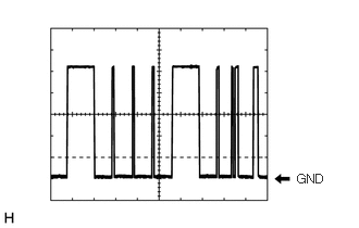
2.844,1.646 3.219,1.813
0.375,0.167
10
false
GND
- HINT:
-
The communication waveform changes according to the surrounding brightness.
| Connector Condition | Tester Connection | Condition | Specified Condition |
|---|---|---|---|
| - | 3 - 5 | Auxiliary battery voltage is not applied to terminals 1 and 2 | 10 kΩ or higher |
| Auxiliary battery voltage is applied to terminals 1 and 2 | Below 1 Ω |
| Connector Condition | Tester Connection | Condition | Specified Condition |
|---|---|---|---|
| - | 3 - 5 | Auxiliary battery voltage is not applied to terminals 1 and 2 | 10 kΩ or higher |
| Auxiliary battery voltage is applied to terminals 1 and 2 | Below 1 Ω |
| Connector Condition | Tester Connection | Condition | Specified Condition |
|---|---|---|---|
| - | 3 - 5 | Auxiliary battery voltage is not applied to terminals 1 and 2 | 10 kΩ or higher |
| Auxiliary battery voltage is applied to terminals 1 and 2 | Below 1 Ω |
| Connector Condition | Tester Connection | Condition | Specified Condition |
|---|---|---|---|
| - | 3 - 5 | Auxiliary battery voltage is not applied to terminals 1 and 2 | 10 kΩ or higher |
| Auxiliary battery voltage is applied to terminals 1 and 2 | Below 1 Ω |
| Connector Condition | Tester Connection | Condition | Specified Condition |
|---|---|---|---|
| - | 3 - 5 | Auxiliary battery voltage is not applied to terminals 1 and 2 | 10 kΩ or higher |
| Auxiliary battery voltage is applied to terminals 1 and 2 | Below 1 Ω |