GF2A TRANSFER / 4WD / AWD TRANSFER ASSEMBLY REASSEMBLY
PROCEDURE

 36111X
1.INSTALL NO. 2 TRANSFER CASE OIL SEAL
36111X
1.INSTALL NO. 2 TRANSFER CASE OIL SEAL
33309B
2.INSTALL OUTPUT SHAFT COMPANION FLANGE SUB-ASSEMBLY
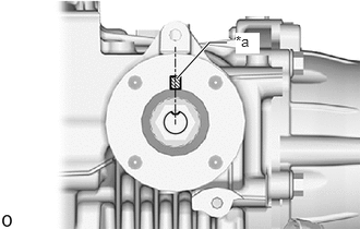
| *a | Matchmark |
Align the matchmark on the output shaft companion flange with the transfer gear groove, and then temporarily install the output shaft companion flange sub-assembly as shown in the illustration.
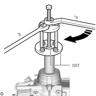
| *a | Turn |
| *b | Hold |
Using SST, install the output shaft companion flange sub-assembly.
- SST
- 09950-30012 (09951-03010, 09953-03010, 09954-03010, 09955-03030)
09956-03090
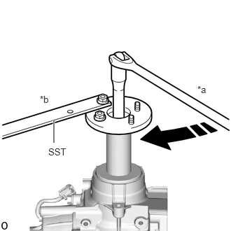
| *a | Turn |
| *b | Hold |
Using SST, temporarily install the output shaft companion flange nut.
- SST
- 09330-00021
- Torque:
- 140 N*m (1428 kgf*cm, 103 ft.*lbf)
- CAUTION:
-
The total preload may be within the standard even when the output shaft companion flange is loose. If the output shaft companion flange is installed in this state, the vehicle may be damaged or lead to a serious accident.
- NOTICE:
-
Tighten the output shaft companion flange nut until there is no more looseness in the output shaft companion flange and it turns to the right and left with the same amount of force.
- NOTICE:
- ·
The total preload may be within the standard even when the output shaft companion flange is loose. If the output shaft companion flange is installed in this state, the vehicle may be damaged or lead to a serious accident.
·Tighten the output shaft companion flange nut until there is no more looseness in the output shaft companion flange and it turns to the right and left with the same amount of force.
- HINT:
-
After temporarily installing the output shaft companion flange nut, be sure to adjust the preoload.
3.INSPECT TOTAL PRELOAD
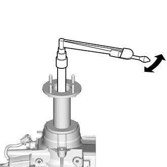
Using a torque wrench, measure the total preload (starting torque) with the teeth of the transfer driven pinion and transfer ring gear in contact.
- HINT:
- ·
The torque wrench should be installed as shown in the illustration.
·For a more accurate measurement, rotate the bearing forward and backward several times before the measurement.
·Use the preload value measured prior to disassembling the transfer assembly as the standard value.
·Adjust within the standard value (Adjustable range within +/- 0.2 N*m of the measured preload value).
If the preload is not as specified, perform the procedures below.
If the measured preoload is higher than the standard value:
Replace the rear drive pinion bearing and transfer pinion bearing spacer, and then adjust the preload again.
If the measured preoload is lower than the standard value:
Tighten the output shaft companion flange nut, and then adjust the preload again.
4.INSTALL OUTPUT SHAFT COMPANION FLANGE NUT
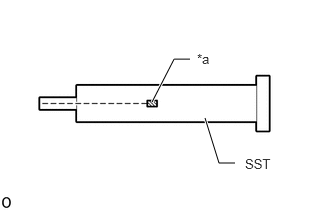
| *a | Matchmark |
Place a matchmark on SST as shown in the illustration.
- SST
- 09930-42010
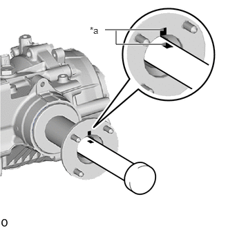
| *a | Matchmark |
Install SST aligned with the matchmark on the output shaft companion flange sub-assembly as shown in the illustration.
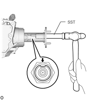
Using SST and a hammer, stake the output shaft companion flange nut.
- NOTICE:
-
Check that the matchmarks are properly aligned.
36111B
5.INSTALL TRANSFER CASE OIL SEAL
36113D
6.INSTALL TRANSFER CASE OIL SEAL RH
Coat the lip of a new drive shaft oil seal RH with MP grease.
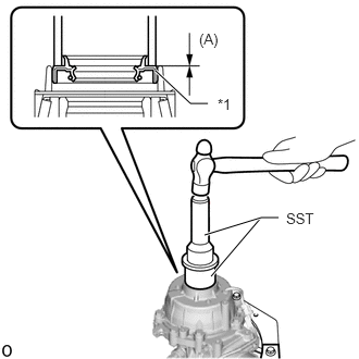
| *1 | Transfer Case Oil Seal RH |
Using SST and a hammer, tap in a new transfer case oil seal RH as shown in the illustration.
- SST
- 09223-46011
09631-32020
- Drive in depth (A):
-0.5 to 0.5 mm (-0.0197 to 0.0196 in.)
- NOTICE:
- ·
Tap the transfer case oil seal RH uniformly so that the transfer case oil seal RH is straight.
·Do not tap the transfer case oil seal RH in too far.
36111H
7.INSTALL TRANSFER CASE BREATHER PLUG
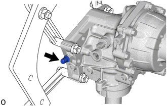
Install a new transfer case breather plug to the transfer case.
- Torque:
- 11.3 N*m (115 kgf*cm, 8 ft.*lbf)
84546
8.INSTALL NO. 1 4 WHEEL DRIVE POSITION SWITCH
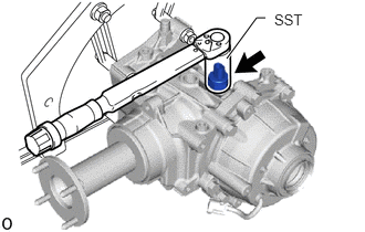
Using SST, install the No. 1 4 wheel drive position switch to the transfer case.
- SST
- 09816-30010
- Torque:
- 40.2 N*m (410 kgf*cm, 30 ft.*lbf)
36111G
9.INSTALL TRANSFER CASE STRAIGHT PIN
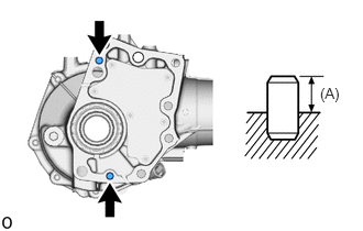
Using a plastic-faced hammer, install the 2 transfer case straight pins to the locations shown in the illustration.
- Drive in depth (A):
10.8 to 11.8 mm (0.426 to 0.464 in.)
36114H
10.INSTALL NO. 2 TRANSFER CASE PLUG
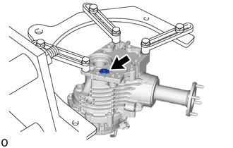
Using a 10 mm socket hexagon wrench, install a new gasket and the No. 2 transfer case plug.
- Torque:
- 39 N*m (398 kgf*cm, 29 ft.*lbf)
36114L
11.INSTALL TRANSFER FILLER PLUG
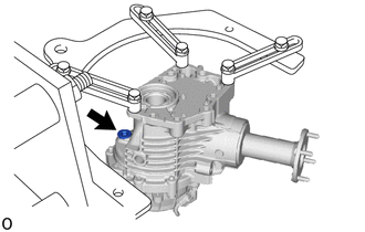
Using a 10 mm socket hexagon wrench, install a new gasket and the transfer filler plug.
- Torque:
- 39 N*m (398 kgf*cm, 29 ft.*lbf)
36114F
12.INSTALL TRANSFER DRAIN PLUG
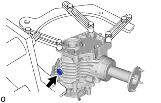
Using a 10 mm socket hexagon wrench, install a new gasket and the transfer drain plug.
- Torque:
- 39 N*m (398 kgf*cm, 29 ft.*lbf)
36114B
13.INSTALL NO. 1 TRANSFER CASE PLUG
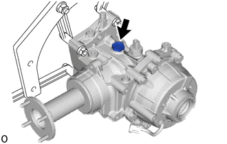
Install a new gasket and the No. 1 transfer case plug.
- Torque:
- 49 N*m (500 kgf*cm, 36 ft.*lbf)
36100
14.REMOVE TRANSFER ASSEMBLY
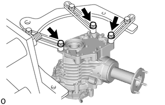
Remove the transfer assembly from the overhaul attachment.
36100A
15.INSTALL TRANSFER AND TRANSAXLE SETTING STUD BOLT
Clean the bolt holes.
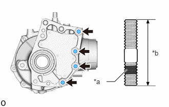
| *a | Adhesive 1324 |
| *b | 64 mm (2.520 in.) |
Using 2 nuts, install 4 new stud bolts in the locations shown in the illustration.
- Torque:
- 39.2 N*m (400 kgf*cm, 29 ft.*lbf)
- NOTICE:
-
Install the shorter threaded part of each stud bolt to the transfer side.