AXLE AND DIFFERENTIAL REAR DIFFERENTIAL CARRIER ASSEMBLY REASSEMBLY
CAUTION / NOTICE / HINT
- NOTICE:
-
Steps 10 to 17 are temporary reassembly procedures for adjustment purposes.
PROCEDURE

 1.INSTALL STRAIGHT PIN
Using a plastic-faced hammer, install the 4 straight pins to the rear differential carrier sub-assembly.
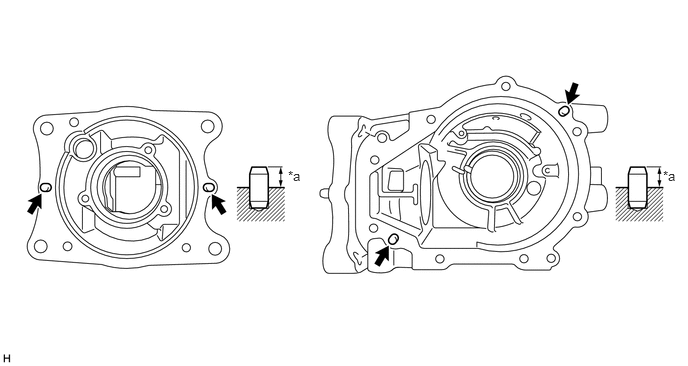
| *a | 8.0 to 9.0 mm (0.315 to 0.354 in.) | - | - |
41183
2.INSTALL REAR DIFFERENTIAL BREATHER PLUG OIL DEFLECTOR
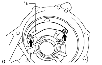
| *a | Arrow Mark |
Using a 5 mm socket hexagon wrench, install the rear differential breather plug oil deflector with the 2 bolts.
- Torque:
- 5.0 N*m (51 kgf*cm, 44 in.*lbf)
- NOTICE:
-
Make sure that the arrow mark faces the front (transmission coupling side) of the vehicle.
3.INSTALL DIFFERENTIAL RING GEAR
Clean the contact surfaces of the rear differential case sub-assembly and differential ring gear.
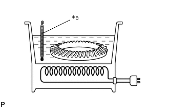
| *a | 100°C (212°F) |
Clean the ring gear set bolt hole.
Heat the differential ring gear to approximately 100°C (212°F) in boiling water.
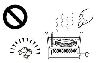
Carefully take the differential ring gear out of the boiling water.
- CAUTION:
-
Use thick gloves to protect your hands as the differential ring gear is hot.
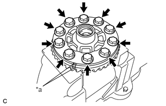
| *a | Matchmark |
After the moisture on the differential ring gear has completely evaporated, quickly install the differential ring gear to the rear differential case sub-assembly.
Align the matchmarks of the rear differential case sub-assembly and differential ring gear, and then install the differential ring gear.
Secure the rear differential case sub-assembly between aluminum plates in a vise.
- NOTICE:
-
Do not overtighten the vise.
Install 10 new rear differential case bolts.
- Torque:
- 90 N*m (918 kgf*cm, 66 ft.*lbf)
- NOTICE:
- ·
The new bolts are coated with heat resistant oil. Do not clean off this coating.
·Install the bolts tightening diametrically opposite bolts uniformly in several passes.
41301A
4.INSTALL REAR DIFFERENTIAL CASE BEARING LH
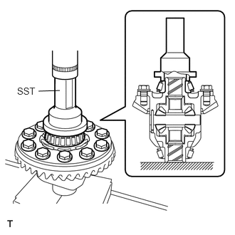
Using SST and a press, press the rear differential case bearing LH (inner race) onto the rear differential case sub-assembly.
- SST
- 09223-50010
- NOTICE:
- ·
If the rear differential case bearing LH (inner race) is damaged, replace the rear differential case bearing LH (inner race) and rear differential case bearing LH (outer race) with new ones as a set.
·If reusing a bearing, coat it with Toyota Genuine Differential gear oil LX SAE 75W-85 API GL-5 or equivalent.
41301A
5.INSTALL REAR DIFFERENTIAL CASE BEARING RH
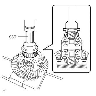
Using SST and a press, press the rear differential case bearing RH (inner race) onto the rear differential case sub-assembly.
- SST
- 09223-50010
- NOTICE:
- ·
If the rear differential case bearing RH (inner race) is damaged, replace the rear differential case bearing RH (inner race) and outer race with new ones as a set.
·If reusing a bearing, coat it with Toyota Genuine Differential gear oil LX SAE 75W-85 API GL-5 or equivalent.
41301A
6.INSTALL REAR DIFFERENTIAL CASE BEARING LH
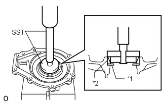
| *1 | Rear Differential Side Gear Shaft Washer |
| *2 | Rear Differential Case Bearing LH (Outer Race) |
Using SST and a press, press the rear differential side gear shaft washer and rear differential case bearing LH (outer race) into the differential side bearing retainer.
- SST
- 09950-60011 (09951-00510, 09951-00620, 09952-06010)
09950-70010 (09951-07100)
- NOTICE:
- ·
Use the removed rear differential side gear shaft washer or use one of the same thickness.
·When replacing a bearing, replace the rear differential case bearing LH (inner race) and rear differential case bearing LH (outer race) races as a set.
·Press in the bearing and washer until they are fit against the end.
·Do not place any load on the rolling contact surface of the bearing.
·Install the rear differential side gear shaft oil seal after performing the teeth contact check and backlash adjustment.
41301A
7.INSTALL REAR DIFFERENTIAL CASE BEARING RH
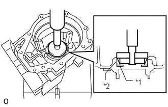
| *1 | Rear Differential Side Gear Shaft Washer |
| *2 | Rear Differential Case Bearing RH (Outer Race) |
Using SST and a press, press the rear differential side gear shaft washer and rear differential case bearing RH (outer race) into the rear differential carrier sub-assembly.
- SST
- 09950-60011 (09951-00510, 09951-00620, 09952-06010)
09950-70010 (09951-07150)
- NOTICE:
- ·
Use the removed rear differential side gear shaft washer or use one of the same thickness.
·When replacing a rear differential case bearing RH, replace the rear differential case bearing RH (inner race) and rear differential case bearing RH (outer race) races as a set.
·Press in the bearing and washer until they are fit against the end.
·Do not place any load on the rolling contact surface of the bearing.
·Install the rear differential side gear shaft oil seal after performing the teeth contact check and backlash adjustment.
41201B
8.INSTALL REAR DRIVE PINION FRONT BEARING
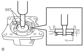
| *1 | Rear Drive Pinion Front Tapered Roller Bearing (Outer Race) |
Using SST and a press, press the rear drive pinion front tapered roller bearing (outer race) into the rear differential carrier sub-assembly.
- SST
- 09950-60011 (09951-00550)
09950-60021 (09951-00680, 09952-06010)
09950-70010 (09951-07100)
- NOTICE:
-
When replacing a rear drive pinion front tapered roller bearing (outer race), replace the inner and outer races as a set.
41201A
9.INSTALL REAR DRIVE PINION REAR BEARING
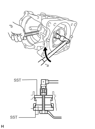
| *a | Turn |
| *b | Hold |
Using SST, bolts, nuts, and washers, install the rear drive pinion rear tapered roller bearing (outer race) to the rear differential carrier sub-assembly.
- SST
- 09950-60011 (09951-00600)
09950-60021 (09951-00680, 09951-00750)
- NOTICE:
-
When replacing the rear drive pinion rear tapered roller bearing (outer race), replace the inner and outer races as a set.
- HINT:
-
Use M12 x P1.25 bolts with shaft lengths of 186 mm (part No. 90101-12159) and M12 x p1.25 nuts (part No. 90179-12051) for the installation.
41201A
10.INSTALL REAR DRIVE PINION REAR BEARING
Install the rear differential drive pinion washer to the differential drive pinion.
- NOTICE:
-
Use the removed rear differential drive pinion washer or use one of the same thickness.
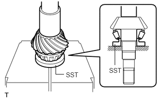
Using SST and a press, press the rear drive pinion rear tapered roller bearing (inner race) into the differential drive pinion.
- SST
- 09506-30012
41231
11.INSTALL REAR DIFFERENTIAL DRIVE PINION BEARING SPACER
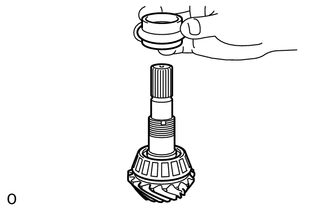
Install the rear differential drive pinion bearing spacer to the differential drive pinion.
- NOTICE:
-
Install the removed rear differential drive pinion bearing spacer, as this is a temporary installation for adjustment.
12.ADJUST DIFFERENTIAL DRIVE PINION PRELOAD
Install the differential drive pinion (with rear drive pinion rear tapered roller bearing inner race) to the rear differential carrier sub-assembly.
Install the rear drive pinion front tapered roller bearing (inner race) and a new rear drive pinion nut to the differential drive pinion.
- NOTICE:
- ·
New bearings are coated with anti-rust oil. If using new bearings, do not clean off this coating.
·If reusing a bearing, coat it with Toyota Genuine Differential gear oil LX SAE 75W-85 API GL-5 or equivalent.
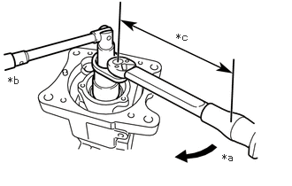
| *a | Turn |
| *b | Hold |
| *c | Torque Wrench Fulcrum Length |
Using SST and torque wrench, gradually tighten a new drive pinion nut within the adjustment range of the differential drive pinion preload.
- SST
- 09556-16011 09564-16020
- Torque:
- Specified tightening torque:
245 N*m (2498 kgf*cm, 181 ft.*lbf) or less
- HINT:
- ·
This torque value is effective when SST is straight to a torque wrench.
·Calculate the torque wrench reading when changing the fulcrum length of the torque wrench.
·When using SST (fulcrum length of 50 mm (1.97 in.)) + torque wrench (fulcrum length of 600 mm (1.97 ft.)): 226 N*m (2305 kgf*cm, 167 ft.*lbf) or less.
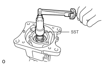
Using SST and a torque wrench, measure the preload (starting torque) of the differential drive pinion.
- SST
- 09556-52010
- Standard Drive Pinion Preload (starting torque):
Bearing Preload New bearing 1.31 to 2.18 N*m (13 to 22 kgf*cm, 12 to 19 in.*lbf) Reused bearing 0.77 to 1.26 N*m (8 to 12 kgf*cm, 7 to 11 in.*lbf)
- NOTICE:
- ·
Measure the preload after rotating the bearing several times in the forward and backward directions to make sure the bearing is operating correctly.
·Record the preload measurement for use with the total preload inspection.
41301
13.INSTALL REAR DIFFERENTIAL CASE SUB-ASSEMBLY
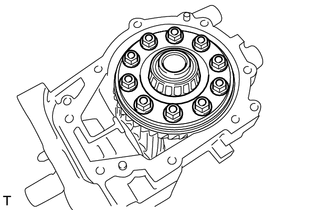
Install the rear differential case sub-assembly to the rear differential carrier sub-assembly.
14.INSTALL DIFFERENTIAL SIDE BEARING RETAINER
Using a scraper, clean the seal packing from the rear differential carrier sub-assembly and differential side bearing retainer, and remove any oil using a cleaning solvent.
- NOTICE:
-
Do not scratch the installation area.
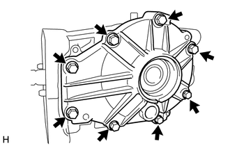
Install the differential side bearing retainer to the rear differential carrier sub-assembly with the 8 bolts.
- Torque:
- 34.3 N*m (350 kgf*cm, 25 ft.*lbf)
15.ADJUST DIFFERENTIAL RING GEAR BACKLASH
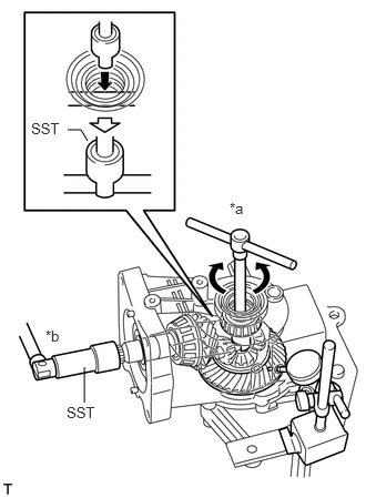
| *a | Turn |
| *b | Hold |
Insert a dial indicator through the rear differential side gear shaft oil seal hole, and set it perpendicular to the edge of a differential ring gear tooth.
Using SST, secure the differential drive pinion.
- SST
- 09556-52010
Using SST, measure the backlash while rotating the rear differential case sub-assembly forward and in reverse.
- SST
- 09564-32011
- Standard:
0.088 to 0.208 mm (0.00347 to 0.00818 in.)
- NOTICE:
-
Measure the ring gear at 3 or more locations.
If the result is not within the specified range, select and install a rear differential side gear shaft washer from the table below.
- HINT:
- ·
Adjust the thickness of the LH and RH differential side gear shaft washers by the same amount each time until the backlash is within the standard range. If the thickness on the LH side is increased, decrease the thickness on the RH side, and if the thickness on the LH side is decreased, increase the thickness on the RH side.
·If the backlash is small, select a thick washer for the RH side and a thin washer for the LH side.
·If the backlash is large, select a thin washer for the RH side and a thick washer for the LH side.
- Rear Differential Side Gear Shaft Washer Type:
Part No. Thickness Identifying Mark Part No. Thickness Identifying Mark 90564-37022 1.59 to 1.61 mm (0.0625 to 0.0633 in.) A0 90564-37040 2.13 to 2.15 mm (0.0839 to 0.0846 in.) B8 90564-37023 1.62 to 1.64 mm (0.0637 to 0.0645 in.) A1 90564-37041 2.16 to 2.18 mm (0.0850 to 0.0858 in.) B9 90564-37024 1.65 to 1.67 mm (0.0650 to 0.0657 in.) A2 90564-37042 2.19 to 2.21 mm (0.0862 to 0.0870 in.) C0 90564-37025 1.68 to 1.70 mm (0.0661 to 0.0669 in.) A3 90564-37043 2.22 to 2.24 mm (0.0874 to 0.0882 in.) C1 90564-37026 1.71 to 1.73 mm (0.0673 to 0.0681 in.) A4 90564-37044 2.25 to 2.27 mm (0.0886 to 0.0894 in.) C2 90564-37027 1.74 to 1.76 mm (0.0685 to 0.0693 in.) A5 90564-37045 2.28 to 2.30 mm (0.0898 to 0.0906 in.) C3 90564-37028 1.77 to 1.79 mm (0.0697 to 0.0705 in.) A6 90564-37046 2.31 to 2.33 mm (0.0909 to 0.0917 in.) C4 90564-37029 1.80 to 1.82 mm (0.0709 to 0.0717 in.) A7 90564-37047 2.34 to 2.36 mm (0.0921 to 0.0929 in.) C5 90564-37030 1.83 to 1.85 mm (0.0720 to 0.0728 in.) A8 90564-37048 2.37 to 2.39 mm (0.0933 to 0.0941 in.) C6 90564-37031 1.86 to 1.88 mm (0.0732 to 0.0740 in.) A9 90564-37049 2.40 to 2.42 mm (0.0945 to 0.0953 in.) C7 90564-37032 1.89 to 1.91 mm (0.0744 to 0.0752 in.) B0 90564-37050 2.43 to 2.45 mm (0.0957 to 0.0965 in.) C8 90564-37033 1.92 to 1.94 mm (0.0756 to 0.0764 in.) B1 90564-37051 2.46 to 2.48 mm (0.0969 to 0.0976 in.) C9 90564-37034 1.95 to 1.97 mm (0.0768 to 0.0776 in.) B2 90564-37052 2.49 to 2.51 mm (0.0980 to 0.0988 in.) D0 90564-37035 1.98 to 2.00 mm (0.0780 to 0.0787 in.) B3 90564-37053 2.52 to 2.54 mm (0.0992 to 0.1000 in.) D1 90564-37036 2.01 to 2.03 mm (0.0792 to 0.0799 in.) B4 90564-37054 2.55 to 2.57 mm (0.1004 to 0.1012 in.) D2 90564-37037 2.04 to 2.06 mm (0.0803 to 0.0811 in.) B5 90564-37055 2.58 to 2.60 mm (0.1016 to 0.1024 in.) D3 90564-37038 2.07 to 2.09 mm (0.0815 to 0.0822 in.) B6 90564-37056 2.61 to 2.63 mm (0.1028 to 0.1035 in.) D4 90564-37039 2.10 to 2.12 mm (0.0827 to 0.0834 in.) B7 90564-37057 2.64 to 2.66 mm (0.1040 to 0.1047 in.) D5
16.ADJUST TOOTH CONTACT BETWEEN RING GEAR AND DRIVE PINION
Remove the 8 bolts and differential side bearing retainer from the rear differential carrier sub-assembly.
Remove the rear differential case sub-assembly.
Uniformly apply a light coat of Prussian Blue on both sides of the differential ring gear teeth.
Install the rear differential case sub-assembly.
Temporarily install the differential side bearing retainer to the differential carrier sub-assembly with the 8 bolts.
Rotate the differential drive pinion several times.
Remove the 8 bolts and differential side bearing retainer from the rear differential carrier sub-assembly.
Check the tooth contact pattern of the differential drive pinion and differential ring gear.
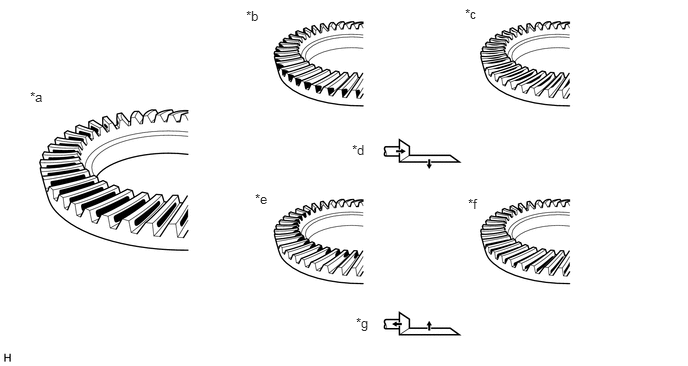
| *a | Proper Contact | *b | Heel Contact |
| *c | Face Contact | *d | Select an adjusting washer that will shift the drive pinion closer to the ring gear (*b, *c) |
| *e | Toe Contact | *f | Flank Contact |
| *g | Select an adjusting washer that will shift the drive pinion away from the ring gear (*e, *f) | - | - |
- NOTICE:
-
Check the tooth contact pattern at 2 or more positions around circumference of the differential ring gear.
In instances of face contact or flank contact, perform the following procedure.
Move and adjust the differential ring gear using the rear differential side gear shaft washer.
- HINT:
-
Adjust the thickness of the LH and RH rear differential side gear shaft washers by the same amount each time. If the thickness on the LH side is increased, decrease the thickness on the RH side, and if the thickness on the LH side is decreased, increase the thickness on the RH side.
In instances of heel contact or toe contact, perform the following procedure.
Select a rear differential drive pinion washer from the table below, and move and adjust the drive pinion.
- Rear Differential Drive Pinion Washer:
Part No. Thickness Identifying Mark Part No. Thickness Identifying Mark 90564-35041 1.695 to 1.705 mm (0.0667 to 0.0671 in.) 41 90564-35071 1.955 to 1.965 mm (0.0770 to 0.0774 in.) 71 90564-35043 1.715 to 1.725 mm (0.0675 to 0.0679 in.) 43 90564-35073 1.975 to 1.985 mm (0.0778 to 0.0781 in.) 73 90564-35045 1.735 to 1.745 mm (0.0683 to 0.0687 in.) 45 90564-35075 1.995 to 2.005 mm (0.0785 to 0.0789 in.) 75 90564-35047 1.755 to 1.765 mm (0.0690 to 0.0695 in.) 47 90564-35077 2.015 to 2.025 mm (0.0793 to 0.0797 in.) 77 90564-35049 1.775 to 1.785 mm (0.0699 to 0.0703 in.) 49 90564-35079 2.035 to 2.045 mm (0.0801 to 0.0805 in.) 79 90564-35051 1.795 to 1.805 mm (0.0707 to 0.0711 in.) 51 90564-35081 2.055 to 2.065 mm (0.0809 to 0.0813 in.) 81 90564-35053 1.815 to 1.825 mm (0.0715 to 0.0719 in.) 53 90564-35083 2.075 to 2.085 mm (0.0817 to 0.0821 in.) 83 90564-35055 1.835 to 1.845 mm (0.0722 to 0.0726 in.) 55 90564-35085 2.095 to 2.105 mm (0.0825 to 0.0829 in.) 85 90564-35057 1.855 to 1.865 mm (0.0730 to 0.0734 in.) 57 90564-35087 2.115 to 2.125 mm (0.0833 to 0.0837 in.) 87 90564-35059 1.875 to 1.885 mm (0.0738 to 0.0742 in.) 59 90564-35089 2.135 to 2.145 mm (0.0841 to 0.0844 in.) 89 90564-35061 1.895 to 1.905 mm (0.0746 to 0.0750 in.) 61 90564-35091 2.155 to 2.165 mm (0.0848 to 0.0852 in.) 91 90564-35063 1.915 to 1.925 mm (0.0754 to 0.0758 in.) 63 90564-35093 2.175 to 2.185 mm (0.0856 to 0.0860 in.) 93 90564-35065 1.935 to 1.945 mm (0.0762 to 0.0766 in.) 65 90564-35095 2.195 to 2.205 mm (0.0864 to 0.0868 in.) 95
If the tooth contact pattern has been adjusted, recheck the backlash, preload and tooth contact pattern.
17.INSPECT TOTAL PRELOAD
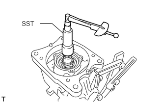
Using SST and a torque wrench, measure the starting torque with the teeth of the differential drive pinion and differential ring gear in contact.
- SST
- 09556-52010
- NOTICE:
-
Measure the preload after rotating the case bearing several times in the forward and backward directions to make sure the bearing is operating correctly.
- Standard drive pinion preload:
Item Specified Condition New bearing Drive pinion preload + 1.18 to 1.90 N*m (12 to 19 kgf*cm, 11 to 16 in.*lbf) Reused bearing Drive pinion preload + 0.58 to 1.01 N*m (6 to 10 kgf*cm, 5 to 8 in.*lbf)
If the result is not within the specified range, perform the following procedures.
Select and install another side gear shaft washer RH.
Recheck the backlash, preload and tooth contact pattern.
18.REMOVE DIFFERENTIAL SIDE BEARING RETAINER
Remove the 8 bolts and differential side bearing retainer from the rear differential carrier sub-assembly.
41301
19.REMOVE REAR DIFFERENTIAL CASE SUB-ASSEMBLY
Remove the rear differential case sub-assembly from the rear differential carrier sub-assembly.
20.REMOVE DIFFERENTIAL DRIVE PINION
Remove the differential drive pinion from the rear differential carrier sub-assembly.
Remove the rear differential drive pinion bearing spacer from the differential drive pinion.
41231
21.INSTALL REAR DIFFERENTIAL DRIVE PINION BEARING SPACER
Install a new rear differential drive pinion bearing spacer to the differential drive pinion.
22.INSTALL DIFFERENTIAL DRIVE PINION
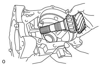
Install the differential drive pinion to the rear differential carrier sub-assembly.
41204B
23.TEMPORARILY TIGHTEN REAR DRIVE PINION NUT
Apply hypoid gear oil LSD to the threads of the rear drive pinion nut and its seating surface.
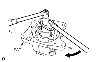
| *a | Turn |
| *b | Hold |
Using SST, temporarily tighten the rear drive pinion nut to the differential drive pinion.
- SST
- 09556-16011 09564-16020
24.ADJUST DIFFERENTIAL DRIVE PINION PRELOAD
Using SST and a torque wrench, check the starting torque.
- SST
- 09556-52010
- NOTICE:
- ·
Adjust the preload after rotating the case bearing several times in the forward and backward directions to make sure the bearing is operating correctly.
·Adjust the preload so that it matches the drive pinion temporary adjustment starting torque.
- Standard drive pinion preload:
Bearing Specified Condition New bearing 1.31 to 2.18 N*m (13 to 22 kgf*cm, 12 to 19 in.*lbf) Reused bearing 0.77 to 1.26 N*m (8 to 12 kgf*cm, 7 to 11 in.*lbf)
| *a | Turn |
| *b | Hold |
| *c | Torque Wrench Fulcrum Length |
If the preload is insufficient, use SST to tighten the drive pinion nut 5 to 10° at a time. Measure the starting torque and repeat the adjustment as necessary until the preload matches the specified torque.
- SST
- 09556-52010 09564-16020
If the tightening torque of the rear drive pinion nut exceeds 245 N*m but the preload is still insufficient, loosen the rear drive pinion nut. Then check if the rear drive pinion nut and differential drive pinion screw threads are damaged.
- HINT:
- ·
This torque value is effective when SST is straight to a torque wrench.
·Calculate the torque wrench reading when changing the fulcrum length of the torque wrench.
·When using SST (fulcrum length of 50 mm (1.97 in.)) + torque wrench (fulcrum length of 600 mm (1.97 ft.)): 226 N*m (2305 kgf*cm, 167 ft.*lbf) or less.
If there are no problems, replace the rear differential drive pinion bearing spacer, apply hypoid gear oil LSD to its threads and repeat the procedure above.
41301
25.INSTALL REAR DIFFERENTIAL CASE SUB-ASSEMBLY
Install the rear differential case sub-assembly to the rear differential carrier sub-assembly.
26.INSTALL DIFFERENTIAL SIDE BEARING RETAINER
Install the differential side bearing retainer to the rear differential carrier with the 8 bolts.
- Torque:
- 34.3 N*m (350 kgf*cm, 25 ft.*lbf)
27.INSPECT DIFFERENTIAL RING GEAR BACKLASH
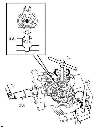
| *a | Turn |
| *b | Hold |
Insert a dial indicator into the rear differential side gear shaft oil seal hole, and place it perpendicular to the edge of a ring gear tooth.
Using SST, secure the drive pinion.
- SST
- 09556-52010
Using SST, check the backlash while rotating the rear differential case sub-assembly forward and in reverse.
- SST
- 09564-32011
- Standard:
0.088 to 0.208 mm (0.00347 to 0.00818 in.)
- NOTICE:
-
Measure the ring gear at 3 or more locations.
28.INSPECT TOTAL PRELOAD
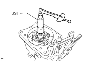
Using SST and a torque wrench, measure the preload (starting torque) of the backlash between the differential drive pinion and differential ring gear.
- SST
- 09556-52010
- NOTICE:
-
Measure the preload after rotating the case bearing several times in the forward and backward directions to make sure the bearing is operating correctly.
- Standard drive pinion preload:
Bearing Specified Condition New bearing Drive pinion preload + 1.18 to 1.90 N*m (12 to 19 kgf*cm, 10 to 16 in.*lbf) Reused bearing Drive pinion preload + 0.58 to 1.01 N*m (6 to 11 kgf*cm, 5 to 8 in.*lbf)
If the result is not within the specified range, perform the following procedures.
Select and install another side gear shaft washer RH.
Recheck the backlash, preload and tooth contact pattern.
29.REMOVE DIFFERENTIAL SIDE BEARING RETAINER
Remove the 8 bolts and differential side bearing retainer from the rear differential carrier sub-assembly.
30.INSTALL DIFFERENTIAL SIDE BEARING RETAINER
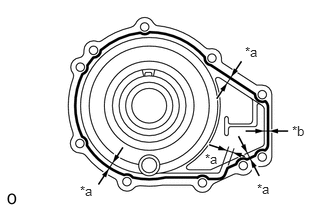
| *a | 6 mm (0.236 in.) |
| *b | 3 mm (0.118 in.) |
Apply seal packing 1281 to the areas of the differential side bearing retainer shown in the illustration.
- Seal packing:
Toyota Genuine Seal Packing 1281, Three Bond 1281 or equivalent
- NOTICE:
- ·
Apply seal packing 1281 in a continuous line, approximately 2 to 3 mm (0.0788 to 0.118 in.) in diameter.
·Overlap the seal packing at least 10 mm (0.394 in.) at the beginning and the end of application.
·Install the differential side bearing retainer within 3 minutes of application.
Install the differential side bearing retainer to the rear differential carrier sub-assembly with the 8 bolts.
- Torque:
- 34.3 N*m (350 kgf*cm, 25 ft.*lbf)
- NOTICE:
-
After installing the cover, leave the vehicle for at least 1 hour without driving or adding oil. After this, avoid any sudden acceleration or deceleration for the next 12 hours.
31.INSPECT TOTAL PRELOAD
Using SST and a torque wrench, check the starting torque with the teeth of the differential drive pinion and differential ring gear in contact.
- SST
- 09556-52010
- NOTICE:
-
Measure the preload after rotating the case bearing several times in the forward and backward directions to make sure the bearing is operating correctly.
- Standard drive pinion preload:
Bearing Specified Condition New bearing Drive pinion preload + 1.18 to 1.90 N*m (12 to 19 kgf*cm, 10 to 16 in.*lbf) Reused bearing Drive pinion preload + 0.58 to 1.01 N*m (6 to 10 kgf*cm, 5 to 8 in.*lbf)
32.INSPECT DIFFERENTIAL RING GEAR BACKLASH
| *a | Turn |
| *b | Hold |
Insert a dial indicator through the rear differential side gear shaft oil seal hole, and set it perpendicular to the edge of a ring gear tooth.
Using SST, secure the drive pinion.
- SST
- 09556-52010
Using SST, check the backlash while rotating the rear differential case sub-assembly forward and in reverse.
- SST
- 09564-32011
- Standard backlash:
0.088 to 0.208 mm (0.000347 to 0.00818 in.)
- NOTICE:
-
Measure the ring gear at 3 or more locations.
41204B
33.INSTALL REAR DRIVE PINION NUT
Using a chisel and hammer, stake the rear drive pinion nut.
34.INSTALL DIAPHRAGM OIL SEAL
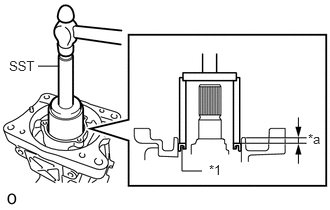
| *1 | Diaphragm Oil Seal |
| *a | Distance |
Using SST and a hammer, tap a new diaphragm oil seal into the rear differential carrier sub-assembly until it reaches the standard value.
- SST
- 09710-30021 (09710-03121)
09950-60011 (09951-00570)
09950-70010 (09951-07100)
- Standard distance:
6.5 to 7.5 mm (0.256 to 0.295 in.) (from the edge of the differential carrier sub-assembly)
- NOTICE:
- ·
Tap the oil seal uniformly so that the oil seal is straight.
·Do not tap the oil seal in too far.
42330G
35.INSTALL REAR DRIVE SHAFT OIL SEAL RH
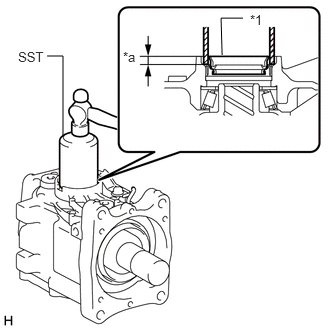
| *1 | Rear Differential Side Gear Shaft Oil Seal |
| *a | Distance |
Using SST and a hammer, tap a new rear drive shaft oil seal RH into the differential carrier until they reach the standard value.
- SST
- 09223-00010
- Standard distance:
6.7 to 7.7 mm (0.264 to 0.303 in.) (from the protruding part of the carrier)
- NOTICE:
- ·
Tap the oil seal uniformly so that the oil seal is straight.
·Do not tap the oil seal in too far.
42340D
36.INSTALL REAR DRIVE SHAFT OIL SEAL LH
- HINT:
-
Perform the same procedure as for the RH side.
41330J
37.INSTALL TRANSMISSION COUPLING SHIM
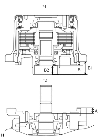
| *1 | Transmission Coupling Assembly |
| *2 | Differential Carrier Sub-assembly |
Using a vernier caliper and precision straightedge, measure dimensions B1 and B2 of the transmission coupling assembly.
Calculate dimension B by subtracting dimension B2 from B1.
- HINT:
- ·
Dimension B = Dimension B1 - Dimension B2
·Dimension B1 is the distance from the installation surface of the transmission coupling assembly to the edge of the bearing.
Using a vernier caliper and precision straightedge, measure dimension A of the rear differential carrier sub-assembly.
- HINT:
-
Dimension A is the distance from the installation surface of the rear differential carrier sub-assembly to the edge of the differential drive pinion.
Select a transmission coupling shim based on the difference between dimensions A and B, and install the shim.
- Transmission Coupling Shim:
Difference of dimension A and B Part No. Thickness Identifying Mark 3.96 to 4.01 mm (0.156 to 0.157 in.) 90564-25024 1.98 to 2.02 mm (0.078 to 0.079 in.) 1 4.26 to 4.31 mm (0.168 to 0.169 in.) 90564-25025 2.28 to 2.32 mm (0.090 to 0.091 in.) 2 4.56 to 4.61 mm (0.180 to 0.181 in.) 90564-25026 2.58 to 2.62 mm (0.102 to 0.103 in.) 3 3.81 to 3.86 mm (0.150 to 0.151 in.) 90564-25027 1.83 to 1.87 mm (0.072 to 0.073 in.) 4 4.11 to 4.16 mm (0.162 to 0.163 in.) 90564-25028 2.13 to 2.17 mm (0.084 to 0.085 in.) 5 4.41 to 4.46 mm (0.174 to 0.175 in.) 90564-25029 2.43 to 2.47 mm (0.096 to 0.097 in.) 6 3.71 to 3.76 mm (0.146 to 0.148 in.) 90564-25031 1.73 to 1.77 mm (0.068 to 0.069 in.) 8 3.76 to 3.81 mm (0.148 to 0.149 in.) 90564-25032 1.78 to 1.82 mm (0.070 to 0.071 in.) 9 3.86 to 3.91 mm (0.152 to 0.153 in.) 90564-25033 1.88 to 1.92 mm (0.074 to 0.075 in.) 10 3.91 to 3.96 mm (0.154 to 0.155 in.) 90564-25034 1.93 to 1.97 mm (0.076 to 0.077 in.) 11 4.01 to 4.06 mm (0.158 to 0.159 in.) 90564-25035 2.03 to 2.07 mm (0.080 to 0.081 in.) 12 4.06 to 4.11 mm (0.160 to 0.161 in.) 90564-25036 2.08 to 2.12 mm (0.082 to 0.083 in.) 13 4.16 to 4.21 mm (0.164 to 0.165 in.) 90564-25037 2.18 to 2.22 mm (0.086 to 0.087 in.) 14 4.21 to 4.26 mm (0.166 to 0.167 in.) 90564-25038 2.23 to 2.27 mm (0.088 to 0.089 in.) 15 4.31 to 4.36 mm (0.170 to 0.171 in.) 90564-25039 2.33 to 2.37 mm (0.092 to 0.093 in.) 16 4.36 to 4.41 mm (0.172 to 0.173 in.) 90564-25040 2.38 to 2.42 mm (0.094 to 0.095 in.) 17 4.46 to 4.51 mm (0.176 to 0.177 in.) 90564-25041 2.48 to 2.52 mm (0.098 to 0.099 in.) 18 4.51 to 4.56 mm (0.178 to 0.179 in.) 90564-25042 2.53 to 2.57 mm (0.100 to 0.101 in.) 19 4.61 to 4.66 mm (0.182 to 0.183 in.) 90564-25043 2.63 to 2.67 mm (0.104 to 0.105 in.) 20 4.66 to 4.71 mm (0.184 to 0.185 in.) 90564-25044 2.68 to 2.72 mm (0.106 to 0.107 in.) 21
41330E
38.INSTALL TRANSMISSION COUPLING CONICAL SPRING WASHER
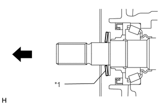
| *1 | Transmission Coupling Conical Spring Washer |

|
Front of the vehicle (transmission coupling assembly side) |
Install the transmission coupling conical spring washer to the rear differential carrier sub-assembly.
- NOTICE:
-
Install the transmission coupling conical spring washer so that the protruding part is facing the front of the vehicle (transmission coupling assembly side).
41330D
39.INSTALL TRANSMISSION COUPLING ASSEMBLY
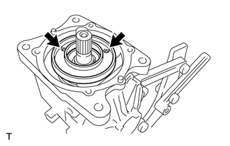
Using a 5 mm socket hexagon wrench, install the yoke to the rear differential carrier sub-assembly with the 2 bolts.
- Torque:
- 5.0 N*m (51 kgf*cm, 44 in.*lbf)
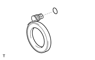
Install a new O-ring to the 4WD linear solenoid.
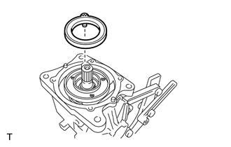
Install the 4WD linear solenoid to the yoke.
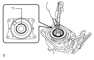
| *1 | Snap Ring |
Using a snap ring expander, install a new snap ring.
Using a scraper, clean the seal packing from the rear differential carrier sub-assembly and transmission coupling assembly, and remove any oil using a cleaning solvent.
- NOTICE:
-
Do not scratch the installation area.
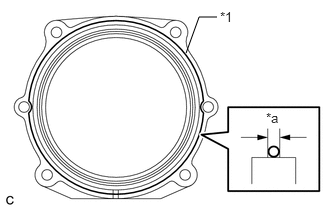
| *1 | Seal Packing |
| *a | 2 to 3 mm (0.0788 to 0.1181 in.) |
Apply seal packing 1281 to the areas of the transmission coupling assembly shown in the illustration.
- Seal packing:
Toyota Genuine Seal Packing 1281, Three Bond 1281 or equivalent
- NOTICE:
- ·
Apply seal packing 1281 in a continuous line, approximately 2 to 3 mm (0.0788 to 0.118 in.) in diameter.
·Overlap the seal packing at least 10 mm (0.394 in.) at the beginning and the end of application.
·Install the transmission coupling assembly within 3 minutes of application.
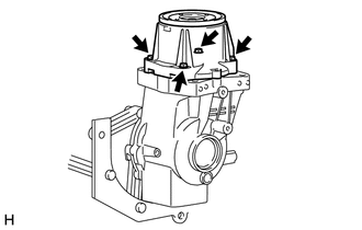
Install the transmission coupling assembly to the rear differential carrier sub-assembly with the 4 bolts.
- Torque:
- 19.6 N*m (200 kgf*cm, 14 ft.*lbf)
41108C
40.INSTALL REAR DIFFERENTIAL CARRIER COVER BREATHER PLUG
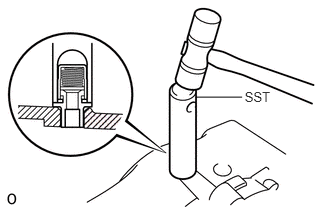
Using SST, install a new rear differential carrier cover breather plug to the rear differential carrier sub-assembly.
- SST
- 09612-07010 (09612-10061)
- NOTICE:
-
Tap the plug in until the flange meets the edge of the rear differential carrier sub-assembly.
41108A
41.INSTALL REAR DIFFERENTIAL CARRIER COVER PLUG
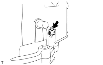
Using an 8 mm socket hexagon wrench, install a new rear differential carrier cover plug to the rear differential carrier sub-assembly.
- Torque:
- 30 N*m (306 kgf*cm, 22 ft.*lbf)
41110H
42.INSTALL REAR DIFFERENTIAL FILLER PLUG
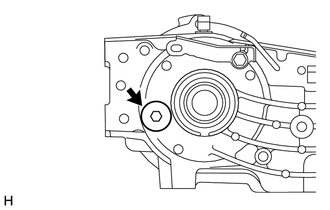
Using a 10 mm socket hexagon wrench, install a new gasket and the rear differential filler plug.
- Torque:
- 39 N*m (398 kgf*cm, 29 ft.*lbf)
41110D
43.INSTALL REAR DIFFERENTIAL DRAIN PLUG
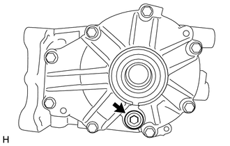
Using a 10 mm socket hexagon wrench, install a new gasket and the rear differential drain plug.
- Torque:
- 39 N*m (398 kgf*cm, 29 ft.*lbf)
44.INSPECT RUNOUT OF TRANSMISSION COUPLING ASSEMBLY
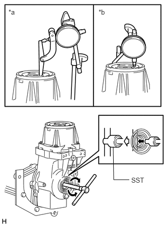
| *a | Vertical Runout |
| *b | Lateral Runout |
Attach a lever probe to a dial indicator and set the probe at a right angle to the inner surface of the transmission coupling assembly.
Using SST, rotate the transmission coupling assembly forward and in reverse and measure the vertical runout.
- SST
- 09564-32011
- Maximum:
0.06 mm (0.00236 in.)
Set the dial indicator at a right angle to the transmission coupling assembly in the position shown in the illustration.
Using SST, rotate the transmission coupling assembly forward and in reverse and measure the lateral runout.
- SST
- 09564-32011
- Maximum:
0.07 mm (0.00276 in.)
45.INSTALL STUD BOLT
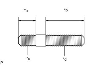
| *a | 12.2 mm (0.480 in.) |
| *b | 26.3 mm (1.04 in.) |
| *c | Propeller Shaft Side |
| *d | Transmission Coupling Assembly Side |
Using 2 nuts, install the 4 stud bolts to the transmission coupling assembly.
- Torque:
- 8.0 N*m (82 kgf*cm, 71 in.*lbf)
- NOTICE:
-
Install the longer threaded part of each bolt to the transmission coupling assembly side.