TELEMATICS TELEMATICS SYSTEM B15C111 GNSS Antenna Circuit Short to Ground B15C113 GNSS Antenna Circuit Open
DESCRIPTION
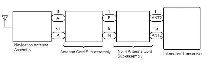
These DTCs are stored when a malfunction occurs in the navigation antenna assembly.
| DTC No. | Detection Item | DTC Detection Condition | Trouble Area |
|---|---|---|---|
| B15C111 | GNSS Antenna Circuit Short to Ground | Current to the telephone antenna assembly is lower than the malfunction threshold for 10 seconds or more when the ignition switch is ON
(Short circuit) |
·
Telematics transceiver ·
Navigation antenna assembly ·
Antenna cord sub-assembly ·
No. 4 antenna cord sub-assembly |
| B15C113 | GNSS Antenna Circuit Open | Current to the telephone antenna assembly is higher than the malfunction threshold for 10 seconds or more when the ignition switch is ON
(Open circuit) |
·
Telematics transceiver ·
Navigation antenna assembly ·
Antenna cord sub-assembly ·
No. 4 antenna cord sub-assembly |
WIRING DIAGRAM
CAUTION / NOTICE / HINT
- NOTICE:
- ·
Depending on the parts that are replaced during vehicle inspection or maintenance, performing initialization, registration or calibration may be needed. Refer to Precaution for Telematics System.
·When replacing the telematics transceiver, make sure to replace it with a new one.
·Before replacing the telematics transceiver, refer to Service Bulletin.
PROCEDURE
Turn the ignition switch off.
Connect the GTS to the DLC3.
Turn the ignition switch to ON and wait for 10 seconds or more.
Turn the GTS on.
Clear the DTCs.
- Body Electrical > Telematics > Clear DTCs
- 50002 459
Check for DTCs and check that no DTCs are output.
- Body Electrical > Telematics > Trouble Codes
- 50001 459
- OK:
No DTCs are output.
- Result:
Proceed to OK NG
OK
NG
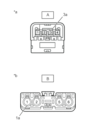
| *a | Front view of wire harness connector
(to Navigation Antenna Assembly) |
| *b | Front view of wire harness connector
(to No. 4 Antenna Cord Sub-assembly) |
Disconnect the antenna connector from the navigation antenna assembly.
Disconnect the antenna connector from the No. 4 antenna cord sub-assembly.
Measure the resistance according to the value(s) in the table below.
- Standard Resistance:
Tester Connection Condition Specified Condition A-3 - B-1 Always Below 1 Ω A-3a - B-1a Always Below 1 Ω A-3 - Body ground Always 10 kΩ or higher
- Result:
Proceed to OK NG
OK
NG
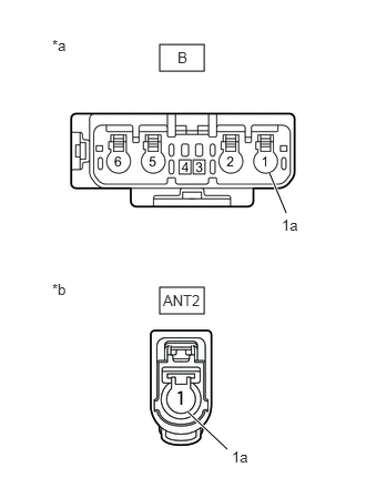
| *a | Front view of wire harness connector
(to Antenna Cord Sub-assembly) |
| *b | Front view of wire harness connector
(to Telematics Transceiver) |
Disconnect the antenna connector from the antenna cord sub-assembly.
Disconnect the antenna connector from the telematics transceiver.
Measure the resistance according to the value(s) in the table below.
- Standard Resistance:
Tester Connection Condition Specified Condition B-1 - ANT2-1 Always Below 1 Ω B-1a - ANT2-1a Always Below 1 Ω B-1 - Body ground Always 10 kΩ or higher
- Result:
Proceed to OK NG
OK
NG
Replace the navigation antenna assembly with a new or known good one.
Clear the DTCs.
- Body Electrical > Telematics > Clear DTCs
- 50002 459
Recheck for DTCs and check that no DTCs are output.
- Body Electrical > Telematics > Trouble Codes
- 50001 459
- OK:
No DTCs are output.
- Result:
Proceed to OK NG
OK
NG
Replace the telematics transceiver with a new one.
- Result:
Proceed to NEXT
NEXT