MAINTENANCE COOLANT(for Inverter) REPLACEMENT
CAUTION / NOTICE / HINT
- CAUTION:
-
To avoid the danger of being burned, do not remove the reserve tank cap or drain cock plug while the coolant (for inverter) is still hot. Pressurized, hot coolant (for inverter) and steam may be released and cause serious burns.
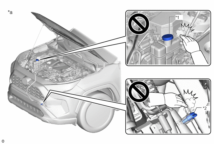 5.667,1.146 5.667,0.563 5.667,0.563 5.833,0.563 true 6.5,3.771 6.583,3.604 6.583,3.604 6.75,3.604 true 5.875,0.5 6.125,0.667 0.25,0.167 10 true *1 6.792,3.542 7.042,3.708 0.25,0.167 10 true *2 0.26,0.302 0.635,0.542 0.375,0.24 12 false *a
*1 Reserve Tank Cap *2 Drain Cock Plug *a Production data from 2019/10 to 2021/08 - -
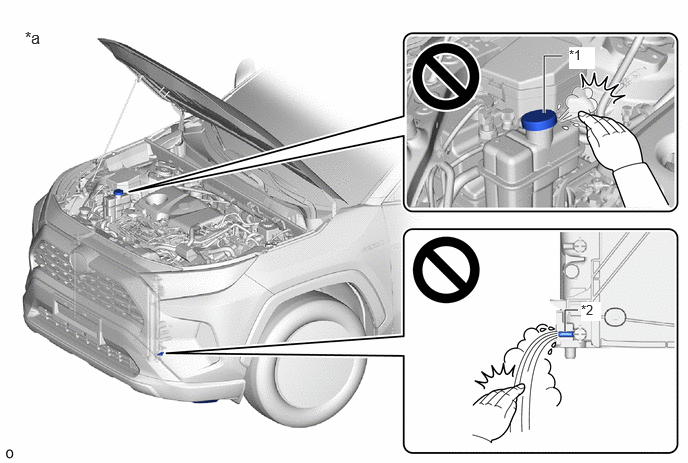 5.667,1.177 5.667,0.583 5.667,0.583 5.854,0.583 true 5.885,3.458 5.885,3.229 5.885,3.229 6.021,3.229 true 0.26,0.292 0.635,0.531 0.375,0.24 12 false *a 5.927,0.49 6.198,0.719 0.271,0.229 10 true *1 6.052,3.146 6.26,3.344 0.208,0.198 10 true *2
*1 Reserve Tank Cap *2 Drain Cock Plug *a Production data from 2021/08 - -
PROCEDURE

 1.DRAIN COOLANT (for Inverter)
- CAUTION:
-
To avoid the danger of being burned, do not remove the reserve tank cap while the coolant (for inverter) is still hot. Pressurized, hot coolant (for inverter) and steam may be released and cause serious burns.
- NOTICE:
- ·
Do not reuse the drained coolant because it may contain foreign matter.
·Collect the drained coolant and measure its volume to establish a benchmark. When adding coolant, make sure to add more coolant than the measured amount.
Production data from 2019/10 to 2021/08:
Remove the reserve tank cap from the inverter reserve tank assembly.
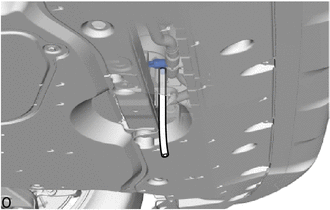
Connect a hose with an inside diameter of 9 mm (0.354 in.) to the drain cock as shown in the illustration.
Loosen the drain cock plug indicated in the illustration and drain the coolant.
Tighten the drain cock plug by hand.
Disconnect the hose from the drain cock.
Production data from 2021/08:
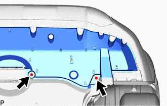
Remove the screw and bolt.
Pull down the No. 1 engine under cover.
- NOTICE:
-
Do not damage the No. 1 engine under cover.
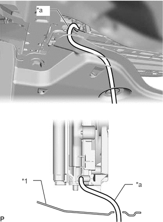
| *1 | No. 1 Engine Under Cover |
| *a | Hose |
Connect a hose with an inside diameter of 8.3 mm (0.327 in.) to the drain cock as shown in the illustration.
Loosen the drain cock plug indicated in the illustration and drain the coolant.
Tighten the drain cock plug by hand.
Disconnect the hose from the drain cock.
2.ADD COOLANT (for Inverter)
- NOTICE:
- ·
Do not reuse the drained coolant because it may contain foreign matter.
·If the vehicle is driven with air in the inverter cooling system, damage may occur and the following DTCs may be stored.
DTC No. Detection Item P0A9300 Inverter "A" Cooling System Performance P0C7396 Motor Electronics Coolant Pump "A" Component Internal Failure P0A001C Motor Electronics Coolant Temperature Sensor Circuit Voltage Out of Range P0A789E Drive Motor "A" Inverter Stuck On P1C5D19 Drive Motor "A" Inverter Circuit Current Above Threshold P0A7A9E Generator Inverter Stuck On P0A949E DC/DC Converter Stuck On P0D3319 DC/DC Converter Circuit Current Above Threshold P0AED1C Drive Motor Inverter Temperature Sensor "A" Circuit Voltage Out of Range P0C381C DC/DC Converter Temperature Sensor "A" Circuit Voltage Out of Range P0C3D1C DC/DC Converter Temperature Sensor "B" Circuit Voltage Out of Range P0E581C DC/DC Converter Temperature Sensor 2 Circuit Voltage Out of Range P1CCC96 DC/DC Converter Enable Component Internal Failure
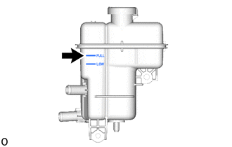
Slowly pour coolant into the inverter reserve tank assembly until it reaches the FULL line.
- Standard Capacity:
- Production data from 2019/10 to 2021/08:
2.0 liters (2.1 US qts, 1.8 Imp. qts)
- Production data from 2021/08:
1.6 liters (1.7 US qts, 1.4 Imp. qts)
- NOTICE:
-
To prevent foreign matter such as dust or dirt from entering the cooling system, make sure to confirm that the container used to add coolant is clean and free of foreign matter.
When using the GTS:
Connect the GTS to the DLC3.
Turn the power switch on (IG).
Enter the following menus: Powertrain / Hybrid Control / Active Test / Activate the Inverter Water Pump.
- Powertrain > Hybrid Control > Active Test
-
Tester Display Activate the Inverter Water Pump - 50004 397 1
- HINT:
-
The inverter water pump with motor assemblycan also be operated using inspection mode.
While adding coolant to the inverter reserve tank assembly to keep the coolant at the FULL line and compensate for the drop in the coolant level as the air bleeds, operate and stop the inverter water pump assembly at 1 minute intervals.
- Standard:
Air bleeding from the inverter cooling system is completed when the noise made by the inverter water pump assembly becomes smaller and the circulation of coolant in the inverter reserve tank assembly improves.
- HINT:
-
Loud noises made by the inverter water pump assembly and poor circulation of coolant in the inverter reserve tank assembly indicate that there is air in the cooling system.
When not using the GTS:
Turn the power switch on (READY). [*1]
Turn the power switch off and add coolant to the FULL line as the coolant level will drop as the air bleeds. [*2]
- NOTICE:
- ·
Be sure to turn the power switch off before adding SLLC.
·Do not work on the components in the engine compartment while the power switch is on (READY) as the engine will operate intermittently.
Repeat steps [*1] and [*2] until air bleeding from the cooling system is completed.
- Standard:
Air bleeding from the inverter cooling system is completed when the noise made by the inverter water pump assembly becomes smaller and the circulation of coolant in the inverter reserve tank assembly improves.
- HINT:
-
Loud noises made by the inverter water pump assembly and poor circulation of coolant in the inverter reserve tank assembly indicate that there is air in the cooling system.
After the air is completely bled from the cooling system, add coolant to the FULL line of inverter reserve tank assembly and install the reserve tank cap.
- NOTICE:
-
Check that the amount of coolant (for Inverter) added is more than the amount drained.
3.INSPECT FOR COOLANT LEAK (for Inverter)