BRAKE CONTROL / DYNAMIC CONTROL SYSTEMS ELECTRONICALLY CONTROLLED BRAKE SYSTEM(for Gasoline Model) C14FE14 Steering Angle Sensor Supply Voltage Circuit Circuit Short to Ground or Open
DESCRIPTION
This DTC is stored when the skid control ECU (brake actuator assembly) receives a +B line open signal from the steering sensor.
| DTC No. | Detection Item | DTC Detection Condition | Trouble Area |
|---|---|---|---|
| C14FE14 | Steering Angle Sensor Supply Voltage Circuit Circuit Short to Ground or Open | With the +BS terminal voltage between 9.6 and 16.5 V, a steering sensor power supply circuit malfunction signal is received from the steering sensor. | ·
Wire harness or connector ·
Steering sensor |
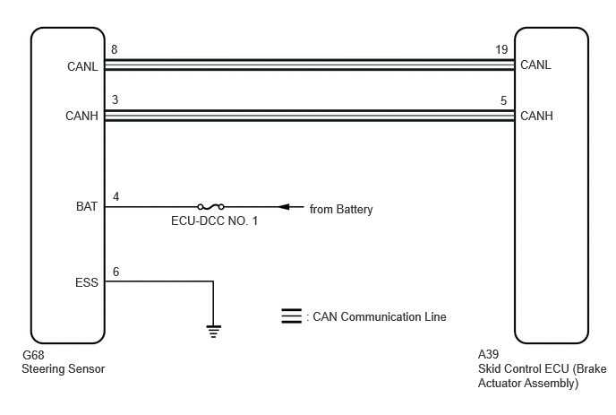
WIRING DIAGRAM
CAUTION / NOTICE / HINT
- NOTICE:
-
Inspect the fuses for circuits related to this system before performing the following procedure.
PROCEDURE
Connect the GTS to the DLC3.
Turn the ignition switch to ON.
Operate the GTS to clear the codes. Enter the following menus: Chassis / Brake/EPB / Trouble Codes.
- Chassis > Brake/EPB > Clear DTCs
- 50002 435
Press the DTC clear button.
- Result:
Proceed to NEXT
NEXT
Connect the GTS to the DLC3.
Start the engine.
Perform a road test under the same malfunction conditions recreated based on the Freeze Frame Data or customer problem analysis.
Read the DTCs following the prompts on the GTS. Enter the following menus: Chassis / Brake/EPB / Trouble Codes.
- Chassis > Brake/EPB > Trouble Codes
- 50001 435
Check if the same DTC is output.
- Result:
Result Proceed to C14FE14 is not output A C14FE14 is output B
A
B
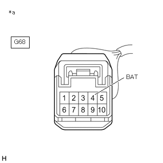
| *a | Front view of wire harness connector
(to Steering Sensor) |
Remove the steering wheel and column cover.
Make sure that there is no looseness at the locking part and the connecting part of the connector.
- OK:
The connector is securely connected.
Disconnect the G68 steering sensor connector.
Check both the connector case and the terminals for deformation and corrosion.
- OK:
No deformation or corrosion.
Measure the voltage according to the value(s) in the table below.
- Standard Voltage:
Tester Connection Condition Specified Condition G68-4 (BAT) - Body ground Always 11 to 14 V
- Result:
Proceed to OK NG
OK
NG