AXLE AND DIFFERENTIAL REAR AXLE CARRIER(for 2WD) INSTALLATION
CAUTION / NOTICE / HINT
- HINT:
- ·
Use the same procedure for the RH and LH sides.
·The following procedure is for the LH side.
PROCEDURE

 1.TEMPORARILY INSTALL REAR AXLE CARRIER SUB-ASSEMBLY
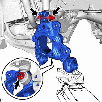
Temporarily install the rear axle carrier sub-assembly to the rear shock absorber assembly with the nut and plate washer.
- NOTICE:
-
Hold the rear axle carrier pin while rotating the nut.
Temporarily install the rear axle carrier sub-assembly to the rear upper control arm assembly with the bolt and nut.
- NOTICE:
- ·
Insert the bolt with the threaded end facing the rear of the vehicle.
·Because the nut has its own stopper, do not turn the nut. Tighten the bolt with the nut secured.
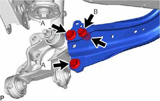
Install the rear trailing arm assembly to the rear axle carrier sub-assembly with the 3 bolts and nut.
- Torque:
- Bolt A : 135 N*m (1377 kgf*cm, 100 ft.*lbf)
- Bolt B : 75 N*m (765 kgf*cm, 55 ft.*lbf)
47354B
2.INSTALL NO. 4 FLEXIBLE HOSE BRACKET
Install the No. 4 flexible hose bracket to the rear axle carrier sub-assembly with the bolt.
- Torque:
- 29 N*m (296 kgf*cm, 21 ft.*lbf)
48720A
3.TEMPORARILY INSTALL REAR NO. 1 SUSPENSION ARM ASSEMBLY
Temporarily install the rear No. 1 suspension arm assembly to the rear axle carrier sub-assembly with the bolt.
- NOTICE:
- ·
Because the nut has its own stopper, do not turn the nut. Tighten the bolt with the nut secured.
·Insert the bolt with the threaded end facing the rear of the vehicle.
48258C
4.INSTALL REAR LOWER COIL SPRING INSULATOR
48231B
5.INSTALL REAR COIL SPRING
6.STABILIZE SUSPENSION
48790
7.INSTALL REAR UPPER CONTROL ARM ASSEMBLY
Install the rear upper control arm assembly to the rear axle carrier sub-assembly with the bolt and nut.
- Torque:
- 73 N*m (744 kgf*cm, 54 ft.*lbf)
- NOTICE:
-
Because the nut has its own stopper, do not turn the nut. Tighten the bolt with the nut secured.
48720A
8.INSTALL REAR NO. 1 SUSPENSION ARM ASSEMBLY
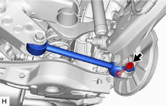
Install the rear No. 1 suspension arm assembly with the bolt.
- Torque:
- 73 N*m (744 kgf*cm, 54 ft.*lbf)
- NOTICE:
-
Because the nut has its own stopper, do not turn the nut. Tighten the bolt with the nut secured.
48740F
9.INSTALL REAR NO. 2 SUSPENSION ARM ASSEMBLY
Install the rear No. 2 suspension arm assembly (rear axle carrier sub-assembly side) with the bolt.
48540
10.INSTALL REAR SHOCK ABSORBER ASSEMBLY
48840A
11.INSTALL REAR STABILIZER LINK ASSEMBLY
42450B
12.INSTALL REAR AXLE HUB AND BEARING ASSEMBLY
42431
13.INSTALL REAR DISC
14.INSTALL REAR DISC BRAKE CALIPER ASSEMBLY
47319F
15.INSTALL REAR FLEXIBLE HOSE
Install the rear flexible hose to the rear flexible hose bracket with the bolt.
- Torque:
- 29 N*m (296 kgf*cm, 21 ft.*lbf)
890C0A
16.INSTALL NO. 2 PARKING BRAKE WIRE ASSEMBLY
Install the No. 2 parking brake wire assembly to the rear trailing arm assembly with the nut.
- Torque:
- 15.5 N*m (158 kgf*cm, 11 ft.*lbf)
Engage the 2 clamps.
Connect the No. 2 parking brake wire assembly connector to the rear axle hub and bearing assembly.
Connect the No. 2 parking brake wire assembly connector to the parking brake actuator assembly.
17.INSTALL REAR WHEEL
48740F
18.INSTALL REAR NO. 2 SUSPENSION ARM ASSEMBLY
Install the rear No. 2 suspension arm assembly (rear suspension member sub-assembly side) with the nut.
19.CONNECT CABLE TO NEGATIVE AUXILIARY BATTERY TERMINAL (for HV Model)
20. INITIALIZATION AFTER RECONNECTING AUXILIARY BATTERY TERMINAL
- HINT:
-
When disconnecting and reconnecting the auxiliary battery, there is an automatic learning function that completes learning when the respective system is used.
21.INSPECT AND ADJUST REAR WHEEL ALIGNMENT
22.CHECK FOR SPEED SENSOR SIGNAL
23.PERFORM INITIALIZATION
| Panoramic View Monitor System | ( 202409,999999,_56,_111825,_0500432,RM100000002O1F6,) 202409,999999,_56,_111825,_0500432,RM100000002O1F6,)
|
| Parking Assist Monitor System | (202409,999999,_56,_111825,_0524148,RM100000002OUWG,)
|