FRONT SUSPENSION FRONT LOWER SUSPENSION ARM INSTALLATION
CAUTION / NOTICE / HINT
- HINT:
- ·
Use the same procedure for the RH side and LH side.
·The following procedure is for the LH side.
PROCEDURE

 48069
1.INSTALL FRONT LOWER NO. 1 SUSPENSION ARM SUB-ASSEMBLY
48069
1.INSTALL FRONT LOWER NO. 1 SUSPENSION ARM SUB-ASSEMBLY
Install the front lower arm bushing stopper to the front lower No. 1 suspension arm sub-assembly.
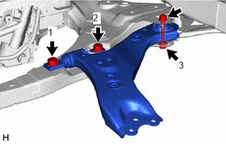
Install the front lower No. 1 suspension arm sub-assembly to the front frame assembly with the 3 bolts and nut in the order shown in the illustration.
- Torque:
- Bolt (1), (2) : 200 N*m (2039 kgf*cm, 148 ft.*lbf)
- Bolt (3) : 135 N*m (1377 kgf*cm, 100 ft.*lbf)
- NOTICE:
-
Because the nut has its own stopper, do not turn the nut. Tighten the bolt with the nut secured.
Connect the front lower No. 1 suspension arm sub-assembly to the front lower ball joint assembly with the bolt and 2 nuts.
- Torque:
- 92 N*m (938 kgf*cm, 68 ft.*lbf)
58166A
2.INSTALL FRONT FLOOR COVER LH (for LH Side)
for M20C-FKS, M20D-FKS: Click hereEngine / Hybrid System>M20C-FKS, M20D-FKS (FUEL)>FUEL TANK>INSTALLATION202203,999999,_51,_111793,_0504184,RM1000000022AQP_01_0100,
for A25D-FXS, A25F-FXS: Click hereEngine / Hybrid System>A25D-FXS, A25F-FXS (FUEL)>FUEL TANK>INSTALLATION202111,999999,_51,_111800,_0504172,RM100000001ZHCY_01_0085,
58165C
3.INSTALL FRONT FLOOR COVER RH (for RH Side)
for M20C-FKS, M20D-FKS: Click hereEngine / Hybrid System>M20C-FKS, M20D-FKS (FUEL)>FUEL TANK>INSTALLATION202203,999999,_51,_111793,_0504184,RM1000000022AQP_01_0102,
for A25D-FXS, A25F-FXS: Click hereEngine / Hybrid System>A25D-FXS, A25F-FXS (ENGINE MECHANICAL)>ENGINE ASSEMBLY>INSTALLATION202303,999999,_51,_111795,_0503439,RM100000002BC9L_01_0353,
53737B
4.INSTALL FRONT FENDER APRON SEAL LH (for LH Side)
for M20C-FKS, M20D-FKS: Click hereEngine / Hybrid System>M20C-FKS, M20D-FKS (ENGINE MECHANICAL)>ENGINE ASSEMBLY>INSTALLATION202409,999999,_51,_111786,_0499722,RM100000002OLFD_01_0290,
for A25D-FXS, A25F-FXS: Click hereEngine / Hybrid System>A25D-FXS, A25F-FXS (ENGINE MECHANICAL)>ENGINE ASSEMBLY>INSTALLATION202303,999999,_51,_111795,_0503439,RM100000002BC9L_01_0290,
53736
5.INSTALL FRONT FENDER APRON SEAL RH (for RH Side)
for M20C-FKS, M20D-FKS: Click hereEngine / Hybrid System>M20C-FKS, M20D-FKS (ENGINE MECHANICAL)>ENGINE ASSEMBLY>INSTALLATION202409,999999,_51,_111786,_0499722,RM100000002OLFD_01_0291,
for A25D-FXS, A25F-FXS: Click hereEngine / Hybrid System>A25D-FXS, A25F-FXS (ENGINE MECHANICAL)>ENGINE ASSEMBLY>INSTALLATION202303,999999,_51,_111795,_0503439,RM100000002BC9L_01_0291,
51468B
6.INSTALL ENGINE UNDER COVER HEAT INSULATOR (for A25D-FXS, A25F-FXS)
51420
7.INSTALL NO. 2 ENGINE UNDER COVER ASSEMBLY
for M20C-FKS, M20D-FKS: Click hereEngine / Hybrid System>M20C-FKS, M20D-FKS (ENGINE MECHANICAL)>ENGINE ASSEMBLY>INSTALLATION202409,999999,_51,_111786,_0499722,RM100000002OLFD_01_0292,
for A25D-FXS, A25F-FXS: Click hereEngine / Hybrid System>A25D-FXS, A25F-FXS (ENGINE MECHANICAL)>ENGINE ASSEMBLY>INSTALLATION202303,999999,_51,_111795,_0503439,RM100000002BC9L_01_0292,
51441
8.INSTALL NO. 1 ENGINE UNDER COVER
for M20C-FKS, M20D-FKS: Click hereEngine / Hybrid System>M20C-FKS, M20D-FKS (ENGINE MECHANICAL)>ENGINE ASSEMBLY>INSTALLATION202409,999999,_51,_111786,_0499722,RM100000002OLFD_01_0293,
for A25D-FXS, A25F-FXS: Click hereEngine / Hybrid System>A25D-FXS, A25F-FXS (ENGINE MECHANICAL)>ENGINE ASSEMBLY>INSTALLATION202303,999999,_51,_111795,_0503439,RM100000002BC9L_01_0293,
53896B
9.INSTALL FRONT FENDER FRONT SPLASH SHIELD LH
for M20C-FKS, M20D-FKS: Click hereEngine / Hybrid System>M20C-FKS, M20D-FKS (ENGINE MECHANICAL)>ENGINE ASSEMBLY>INSTALLATION202409,999999,_51,_111786,_0499722,RM100000002OLFD_01_0350,
for A25D-FXS, A25F-FXS: Click hereEngine / Hybrid System>A25D-FXS, A25F-FXS (ENGINE MECHANICAL)>ENGINE ASSEMBLY>INSTALLATION202303,999999,_51,_111795,_0503439,RM100000002BC9L_01_0330,
53895B
10.INSTALL FRONT FENDER FRONT SPLASH SHIELD RH
for M20C-FKS, M20D-FKS: Click hereEngine / Hybrid System>M20C-FKS, M20D-FKS (ENGINE MECHANICAL)>ENGINE ASSEMBLY>INSTALLATION202409,999999,_51,_111786,_0499722,RM100000002OLFD_01_0349,
for A25D-FXS, A25F-FXS: Click hereEngine / Hybrid System>A25D-FXS, A25F-FXS (ENGINE MECHANICAL)>ENGINE ASSEMBLY>INSTALLATION202303,999999,_51,_111795,_0503439,RM100000002BC9L_01_0331,
11.INSTALL FRONT WHEEL
12.INSPECT AND ADJUST FRONT WHEEL ALIGNMENT
13.PERFORM INITIALIZATION
| Panoramic View Monitor System | ( 202409,999999,_56,_111825,_0500432,RM100000002O1F6,) 202409,999999,_56,_111825,_0500432,RM100000002O1F6,)
|
| Parking Assist Monitor System | (202409,999999,_56,_111825,_0524148,RM100000002OUWG,)
|