POWER OUTLETS (INT) WIRELESS CHARGING SYSTEM(for GTMC Made) Wireless Charger Power Source Circuit
DESCRIPTION
This is the power source circuit for the mobile wireless charger cradle assembly.
WIRING DIAGRAM
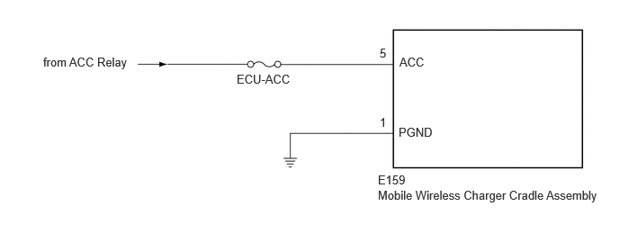
CAUTION / NOTICE / HINT
- NOTICE:
-
Inspect the fuses for circuits related to this system before performing the following procedure.
PROCEDURE
Disconnect the E159 mobile wireless charger cradle assembly connector.
Measure the resistance according to the value(s) in the table below.
- Standard Resistance:
Tester Connection Condition Specified Condition Click Location & Routing(E159)Location & Routingewd_type=routing;type=c;code=E159
Click Connector(E159)Instrument Panel>Instrument Panel Wire / Radio Wiring Sub-Assy / Telephone Computer Wire>Mobile Wireless Charger Cradle Assemblyewd_type=component;type=c;code=E159;pinno=1
E159-1 (PGND) - Body ground Always Below 1 Ω
Measure the voltage according to the value(s) in the table below.
- Standard Voltage:
Tester Connection Condition Specified Condition Click Location & Routing(E159)Location & Routingewd_type=routing;type=c;code=E159
Click Connector(E159)Instrument Panel>Instrument Panel Wire / Radio Wiring Sub-Assy / Telephone Computer Wire>Mobile Wireless Charger Cradle Assemblyewd_type=component;type=c;code=E159;pinno=5
E159-5 (ACC) - Body ground Ignition switch ACC 11 to 14 V
- Result:
Proceed to OK NG
OK
NG