M20C-FKS, M20D-FKS INTAKE / EXHAUST EXHAUST MANIFOLD INSTALLATION
PROCEDURE

 17168
1.INSTALL NO. 2 EXHAUST MANIFOLD HEAT INSULATOR
17168
1.INSTALL NO. 2 EXHAUST MANIFOLD HEAT INSULATOR
Install the No. 2 exhaust manifold heat insulator to the exhaust manifold with the 3 bolts.
- Torque:
- 10 N*m (102 kgf*cm, 7 ft.*lbf)
17141
2.INSTALL EXHAUST MANIFOLD
Install a new exhaust manifold to head gasket to the cylinder head sub-assembly.
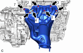
Using a 12 mm deep socket wrench, temporarily install the exhaust manifold to the cylinder head sub-assembly with 7 new nuts.
Using a 12 mm deep socket wrench, tighten the 7 nuts in the order shown in the illustration.
- Torque:
- 26 N*m (265 kgf*cm, 19 ft.*lbf)
17118
3.INSTALL MANIFOLD STAY
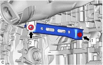
Temporarily install the manifold stay to the exhaust manifold and cylinder block sub-assembly with the bolt and nut.
Tighten the bolt and nut in the order shown in the illustration.
- Torque:
- 43 N*m (438 kgf*cm, 32 ft.*lbf)
17167
4.INSTALL NO. 1 EXHAUST MANIFOLD HEAT INSULATOR
Install the No. 1 exhaust manifold heat insulator to the exhaust manifold with the 2 bolts.
- Torque:
- 10 N*m (102 kgf*cm, 7 ft.*lbf)
5.INSTALL NO. 1 VACUUM TRANSMITTING PIPE SUB-ASSEMBLY
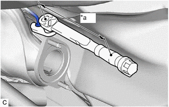
| *a | Torque Wrench Fulcrum Length |
Using a 14 mm union nut wrench, install a new No. 1 vacuum transmitting pipe sub-assembly to the exhaust manifold.
- Torque:
- Specified tightening torque : 30 N*m (306 kgf*cm, 22 ft.*lbf)
- HINT:
- ·
Calculate the torque wrench reading when changing the fulcrum length of the torque wrench.
·When using a 14 mm union nut wrench (fulcrum length of 25 mm (0.984 in.)) + torque wrench (fulcrum length of 180 mm (7.09 in.)): 26.3 N*m (268 kgf*cm, 19 ft.*lbf).
Install the nut.
- Torque:
- 10 N*m (102 kgf*cm, 7 ft.*lbf)
89467B
6.INSTALL AIR FUEL RATIO SENSOR (for Sensor 1)
17410
7.INSTALL FRONT EXHAUST PIPE ASSEMBLY
Install 2 new gaskets to the front exhaust pipe assembly.
Connect the front exhaust pipe assembly to the 2 exhaust pipe supports.
Install the front exhaust pipe assembly to the exhaust manifold and tail exhaust pipe assembly with 2 new bolts and 2 new nuts.
- Torque:
- 43 N*m (438 kgf*cm, 32 ft.*lbf)
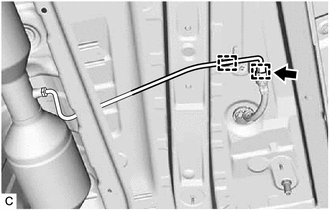
Connect the No. 2 exhaust gas temperature sensor connector.
Attach the 2 clamps.

Connect the No. 1 exhaust gas temperature sensor connector.
Attach the clamp.

| *a | Tube |
| *b | Wire Harness Clamp |
Connect the air fuel ratio sensor (for sensor 2) connector.
Engage the wire harness clamp so that the tube is positioned as shown in the illustration.
8.INSTALL WIRING HARNESS CLAMP BRACKET
58165C
9.INSTALL FRONT FLOOR COVER RH
10.INSPECT FOR EXHAUST GAS LEAK
51420
11.INSTALL NO. 2 ENGINE UNDER COVER ASSEMBLY
12. RESET TOTAL SHORT TRIP ESTIMATE
- HINT:
-
This function is used for initializing the value of "Total Short Trip Estimate Bank 1" which was stored to the ECM when replacing the TWC (front catalyst).