DOOR / HATCH FUEL LID OPENER UNIT INSTALLATION
PROCEDURE

 77305A
1.INSTALL FUEL FILLER OPENING LID SUB-ASSEMBLY
77305A
1.INSTALL FUEL FILLER OPENING LID SUB-ASSEMBLY

| *a | Lip |

|
Protective Tape |
Apply protective tape as shown in the illustration.
- NOTICE:
- ·
Make sure that the lip is as shown in the illustration (a) when applying protective tape.
·Make sure that the lip is not deformed as shown in the illustration (b).

|
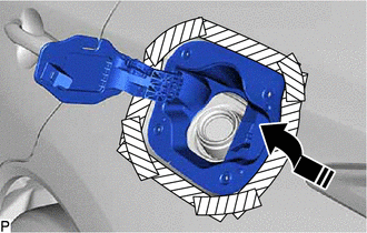
Install in this Direction |
Temporarily install the fuel filler opening lid sub-assembly as shown in the illustration.
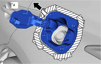
| *a | Protective Tape |
Remove the protective tape as shown in the illustration.
Install the fuel filler opening lid sub-assembly with the 4 screws.
Connect the fuel filler opening lid sub-assembly to the fuel tank filler pipe assembly as shown in the illustration.
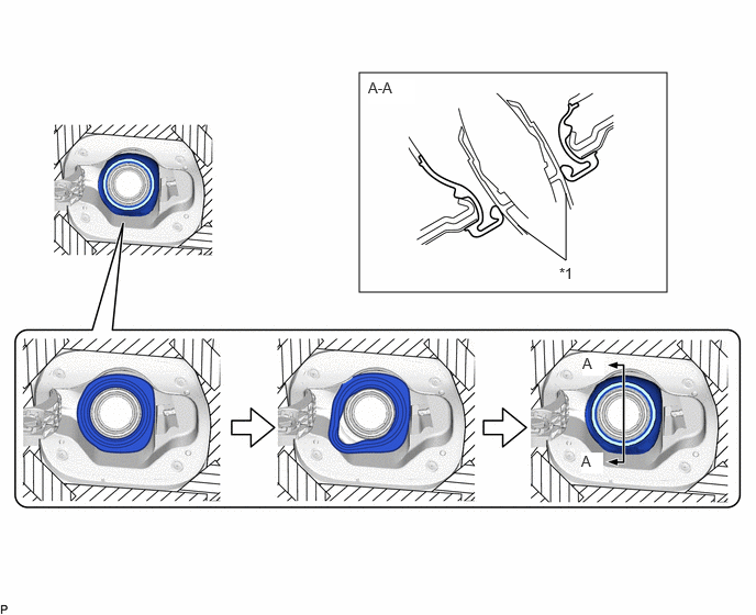
| *1 | Fuel Tank Filler Pipe Assembly | - | - |
Install the fuel inlet box ring as shown in the illustration.
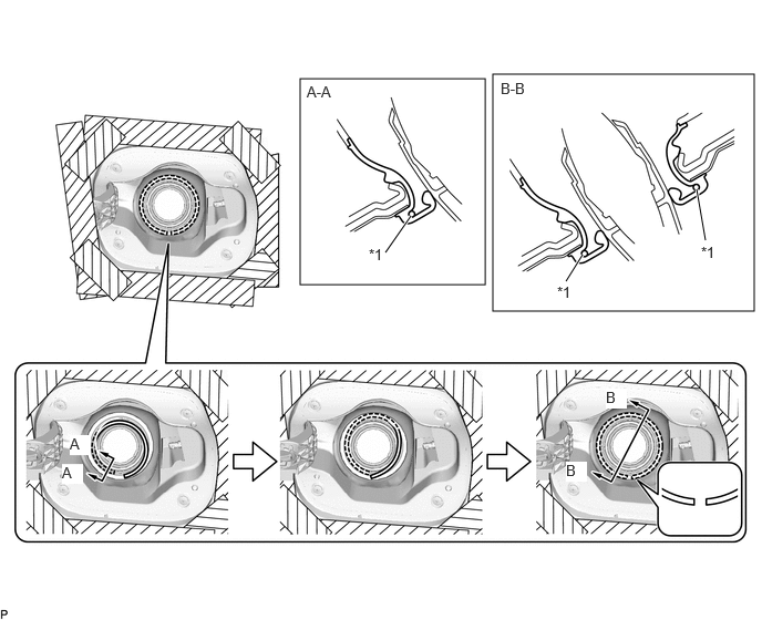
| *1 | Fuel Inlet Box Ring | - | - |
- HINT:
-
Face the end gap of the fuel inlet box ring downward.
77310A
2.INSTALL FUEL TANK CAP ASSEMBLY
Engage the clamp.
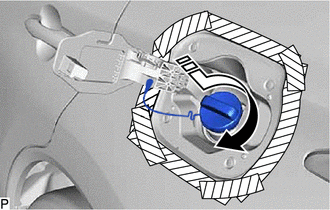
|
|
Install in this Direction |
Install the fuel tank cap assembly as shown in the illustration.
77350
3.INSTALL FUEL FILLER OPENING LID ASSEMBLY
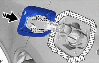
|
|
Install in this Direction |
Engage the 4 guides and claw to install the fuel filler opening lid assembly as shown in the illustration.
Remove the protective tape.
65638
4.CONNECT REAR WHEEL HOUSE LINER LH
Connect the rear wheel house liner LH with the 4 clips.
52592
5.INSTALL REAR BUMPER SIDE SEAL LH
6.INSTALL REAR WHEEL LH
77035
7.CONNECT FUEL LID LOCK CONTROL CABLE SUB-ASSEMBLY (for Gasoline Model)
Engage the claw to install the fuel lid lock control cable sub-assembly.
77030A
8.INSTALL FUEL LID LOCK WITH MOTOR ASSEMBLY (for HV Model)
86150
9.INSTALL NO. 1 SPEAKER ASSEMBLY WITH BOX (for 9 Speakers)
64740C
10.INSTALL DECK TRIM SIDE PANEL ASSEMBLY LH
62552F
11.INSTALL REAR SEAT SIDE GARNISH LH
71304C
12.INSTALL REAR SEATBACK HINGE SUB-ASSEMBLY LH
73706
13.INSTALL CHILD RESTRAINT SEAT ANCHOR BRACKET SUB-ASSEMBLY LH
62332C
14.INSTALL REAR DOOR OPENING TRIM WEATHERSTRIP LH
58467H
15.INSTALL NO. 3 BATTERY SERVICE COVER BOARD (for HV Model)
67918A
16.INSTALL REAR DOOR SCUFF PLATE LH
58577E
17.INSTALL REAR NO. 1 FLOOR MAT SUPPORT SIDE PLATE
18.INSTALL REAR SEATBACK BOARD CARPET ASSEMBLY RH (for SFTM Made)
19.INSTALL REAR SEATBACK BOARD CARPET ASSEMBLY RH (for GTMC Made)
58387B
20.INSTALL REAR FLOOR FINISH PLATE
64779
21.INSTALL SPARE WHEEL COVER TRAY
58417
22.INSTALL REAR NO. 3 FLOOR BOARD
23.CONNECT CABLE TO NEGATIVE AUXILIARY BATTERY TERMINAL
for M20C-FKS, M20D-FKS:
for A25D-FXS, A25F-FXS:
24. INITIALIZATION AFTER RECONNECTING AUXILIARY BATTERY TERMINAL
- HINT:
-
When disconnecting and reconnecting the battery, there is an automatic learning function that completes learning when the respective system is used.
65351A
25.INSTALL BATTERY HOLE COVER (for HV Model)
58416K
26.INSTALL REAR NO. 2 FLOOR BOARD (for HV Model)
27.INSTALL REAR SEATBACK ASSEMBLY LH (for SFTM Made)
28.INSTALL REAR SEATBACK ASSEMBLY LH (for GTMC Made)
72693
29.INSTALL REAR SEAT CUSHION LOCK HOOK (for SFTM Made)
72693
30.INSTALL REAR SEAT CUSHION LOCK HOOK (for GTMC Made)
31.INSTALL REAR SEAT CUSHION ASSEMBLY (for SFTM Made)
32.INSTALL REAR SEAT CUSHION ASSEMBLY (for GTMC Made)
71940A
33.INSTALL REAR SEAT HEADREST ASSEMBLY (for SFTM Made)
71940A
34.INSTALL REAR SEAT HEADREST ASSEMBLY (for GTMC Made)
58410B
35.INSTALL DECK BOARD ASSEMBLY