NETWORKING LIN COMMUNICATION SYSTEM TERMINALS OF ECU
CHECK POWER DISTRIBUTION BOX ASSEMBLY AND MAIN BODY ECU (MULTIPLEX NETWORK BODY ECU)
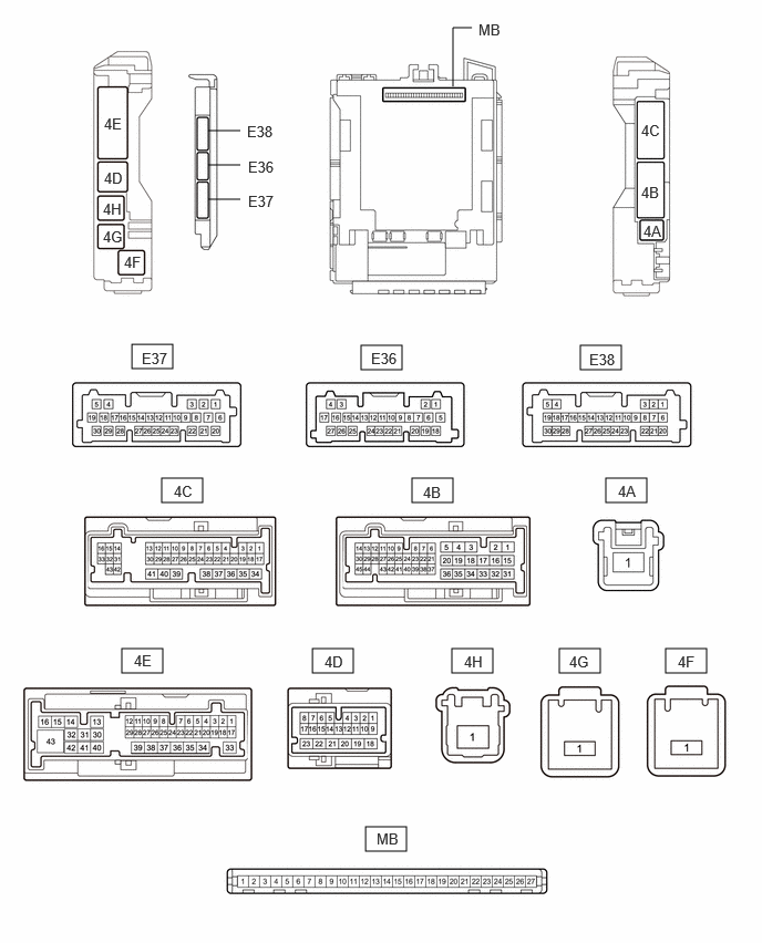
Disconnect the MB main body ECU (multiplex network body ECU) connector.
Measure the voltage and resistance according to the value(s) in the table below.
- HINT:
-
Measure the values on the wire harness side with the connectors disconnected.
| Terminal No. (Symbol) | Terminal Description | Condition | Specified Condition |
|---|---|---|---|
| MB-13 (GND1) - Body ground | Ground | Always | Below 1 Ω |
| MB-26 (BECU) - Body ground | Auxiliary battery power supply | Ignition switch off*1
Always*2 |
11 to 14 V |
| MB-27 (IGR) - Body ground | IG power supply | Ignition switch ON | 11 to 14 V |
| Ignition switch off | Below 1 V |
*1: for HV Model
*2: for Gasoline Model
Reconnect the MB main body ECU (multiplex network body ECU) connector.
Check for pulses according to the value(s) in the table below.
| Terminal No. (Symbol) | Terminal Description | Condition | Specified Condition |
|---|---|---|---|
| 4E-17 - Body ground | LIN communication line | Ignition switch ON | Pulse generation |
| 4B-37 - Body ground* | LIN communication line | Ignition switch ON | Pulse generation |
*: w/ Panoramic Fixed Moonroof with One-touch Frosted Glass Control System
CHECK MULTIPLEX NETWORK MASTER SWITCH ASSEMBLY

Disconnect the I2 multiplex network master switch assembly connector.
Measure the voltage and resistance according to the value(s) in the table below.
- HINT:
-
Measure the values on the wire harness side with the connector disconnected.
| Terminal No. (Symbol) | Terminal Description | Condition | Specified Condition |
|---|---|---|---|
| I2-11 (B) - Body ground | Auxiliary battery power supply | Ignition switch off*1
Always*2 |
11 to 14 V |
| I2-12 (GND) - Body ground | Ground | Always | Below 1 Ω |
*1: for HV Model
*2: for Gasoline Model
Reconnect the I2 multiplex network master switch assembly connector.
Check for pulses according to the value(s) in the table below.
| Terminal No. (Symbol) | Terminal Description | Condition | Specified Condition |
|---|---|---|---|
| I2-17 (LIN1) - Body ground | LIN communication line | Ignition switch ON | Pulse generation |
| I2-16 (LIN2) - Body ground | LIN communication line | Ignition switch ON | Pulse generation |
CHECK POWER WINDOW REGULATOR MOTOR ASSEMBLY (DRIVER DOOR)

Disconnect the G4 power window regulator motor assembly (driver door) connector.
Measure the voltage and resistance according to the value(s) in the table below.
- HINT:
-
Measure the values on the wire harness side with the connector disconnected.
| Terminal No. (Symbol) | Terminal Description | Condition | Specified Condition |
|---|---|---|---|
| G4-2 (B) - Body ground | Auxiliary battery power supply | Ignition switch off*1
Always*2 |
11 to 14 V |
| G4-1 (GND) - Body ground | Ground | Always | Below 1 Ω |
*1: for HV Model
*2: for Gasoline Model
Reconnect the G4 power window regulator motor assembly (driver door) connector.
Check for pulses according to the value(s) in the table below.
| Terminal No. (Symbol) | Terminal Description | Condition | Specified Condition |
|---|---|---|---|
| G4-9 (LIN) - Body ground | LIN communication line | Ignition switch ON | Pulse generation |
CHECK POWER WINDOW REGULATOR MOTOR ASSEMBLY (FRONT PASSENGER DOOR)
Disconnect the G5 power window regulator motor assembly (front passenger door) connector.
Measure the voltage and resistance according to the value(s) in the table below.
- HINT:
-
Measure the values on the wire harness side with the connector disconnected.
| Terminal No. (Symbol) | Terminal Description | Condition | Specified Condition |
|---|---|---|---|
| G5-2 (B) - Body ground | Auxiliary battery power supply | Ignition switch off*1
Always*2 |
11 to 14 V |
| G5-1 (GND) - Body ground | Ground | Always | Below 1 Ω |
*1: for HV Model
*2: for Gasoline Model
Reconnect the G5 power window regulator motor assembly (front passenger door) connector.
Check for pulses according to the value(s) in the table below.
| Terminal No. (Symbol) | Terminal Description | Condition | Specified Condition |
|---|---|---|---|
| G5-9 (LIN) - Body ground | LIN communication line | Ignition switch ON | Pulse generation |
CHECK POWER WINDOW REGULATOR MOTOR ASSEMBLY (REAR RH DOOR)
Disconnect the H5 power window regulator motor assembly (rear RH door) connector.
Measure the voltage and resistance according to the value(s) in the table below.
- HINT:
-
Measure the values on the wire harness side with the connector disconnected.
| Terminal No. (Symbol) | Terminal Description | Condition | Specified Condition |
|---|---|---|---|
| H5-2 (B) - Body ground | Auxiliary battery power supply | Ignition switch off*1
Always*2 |
11 to 14 V |
| H5-1 (GND) - Body ground | Ground | Always | Below 1 Ω |
*1: for HV Model
*2: for Gasoline Model
Reconnect the H5 power window regulator motor assembly (rear RH door) connector.
Check for pulses according to the value(s) in the table below.
| Terminal No. (Symbol) | Terminal Description | Condition | Specified Condition |
|---|---|---|---|
| H5-9 (LIN) - Body ground | LIN communication line | Ignition switch ON | Pulse generation |
CHECK POWER WINDOW REGULATOR MOTOR ASSEMBLY (REAR LH DOOR)
Disconnect the H6 power window regulator motor assembly (rear LH door) connector.
Measure the voltage and resistance according to the value(s) in the table below.
- HINT:
-
Measure the values on the wire harness side with the connector disconnected.
| Terminal No. (Symbol) | Terminal Description | Condition | Specified Condition |
|---|---|---|---|
| H6-2 (B) - Body ground | Auxiliary battery power supply | Ignition switch off*1
Always*2 |
11 to 14 V |
| H6-1 (GND) - Body ground | Ground | Always | Below 1 Ω |
*1: for HV Model
*2: for Gasoline Model
Reconnect the H6 power window regulator motor assembly (rear LH door) connector.
Check for pulses according to the value(s) in the table below.
| Terminal No. (Symbol) | Terminal Description | Condition | Specified Condition |
|---|---|---|---|
| H6-9 (LIN) - Body ground | LIN communication line | Ignition switch ON | Pulse generation |
CHECK ROOF SUNSHADE ECU (SLIDING ROOF DRIVE GEAR ASSEMBLY) (w/ Panoramic Fixed Moonroof with One-touch Frosted Glass Control System)

Disconnect the Q2 roof sunshade ECU (sliding roof drive gear assembly) connector.
Measure the voltage and resistance according to the value(s) in the table below.
- HINT:
-
Measure the values on the wire harness side with the connector disconnected.
| Terminal No. (Symbol) | Terminal Description | Condition | Specified Condition |
|---|---|---|---|
| Q2-10 (B) - Body ground | Auxiliary battery power supply | Ignition switch off*1
Always*2 |
11 to 14 V |
| Q2-5 (E) - Body ground | Ground | Always | Below 1 Ω |
*1: for HV Model
*2: for Gasoline Model
Reconnect the Q2 roof sunshade ECU (sliding roof drive gear assembly) connector.
Check for pulses according to the value(s) in the table below.
| Terminal No. (Symbol) | Terminal Description | Condition | Specified Condition |
|---|---|---|---|
| Q2-7 (MPX1) - Body ground | LIN communication line | Ignition switch ON | Pulse generation |
CHECK CERTIFICATION ECU (SMART KEY ECU ASSEMBLY)
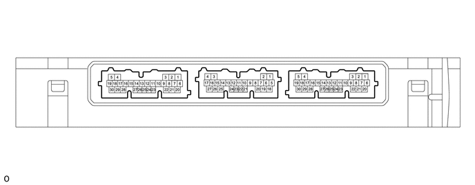
Disconnect the E52 certification ECU (smart key ECU assembly) connector.
Measure the voltage and resistance according to the value(s) in the table below.
- HINT:
-
Measure the values on the wire harness side with the connector disconnected.
| Terminal No. (Symbol) | Terminal Description | Condition | Specified Condition |
|---|---|---|---|
| E52-6 (+B) - Body ground | Auxiliary battery power supply | Ignition switch off*1
Always*2 |
11 to 14 V |
| E52-29 (E) - Body ground | Ground | Always | Below 1 Ω |
*1: for HV Model
*2: for Gasoline Model
Reconnect the E52 certification ECU (smart key ECU assembly) connector.
Check for pulses according to the value(s) in the table below.
| Terminal No. (Symbol) | Terminal Description | Condition | Specified Condition |
|---|---|---|---|
| E52-8 (LIN) - Body ground | LIN communication line | Ignition switch ON | Pulse generation |
CHECK ID CODE BOX (IMMOBILISER CODE ECU)

Disconnect the E55 ID code box (immobiliser code ECU) connector.
Measure the voltage and resistance according to the value(s) in the table below.
- HINT:
-
Measure the values on the wire harness side with the connector disconnected.
| Terminal No. (Symbol) | Terminal Description | Condition | Specified Condition |
|---|---|---|---|
| E55-5 (GND) - Body ground | Ground | Ignition switch off*1
Always*2 |
Below 1 Ω |
| E55-1 (+B) - Body ground | +B power supply | Always | 11 to 14 V |
*1: for HV Model
*2: for Gasoline Model
Reconnect the E55 ID code box (immobiliser code ECU) connector.
Check for pulses according to the value(s) in the table below.
| Terminal No. (Symbol) | Terminal Description | Condition | Specified Condition |
|---|---|---|---|
| E55-2 (LIN1) - Body ground | LIN communication line | Ignition switch ON | Pulse generation |
CHECK KICK DOOR CONTROL SENSOR (w/ Hands Free Power Back Door)

Disconnect the S14 kick door control sensor connector.
Measure the resistance and voltage according to the value(s) in the table below.
| Terminal No. (Symbol) | Terminal Description | Condition | Specified Condition |
|---|---|---|---|
| S14-3 (B) - Body ground | Auxiliary battery power supply | Ignition switch off*1
Always*2 |
11 to 14 V |
| S14-4 (GND) - Body ground | Ground | Always | Below 1 Ω |
*1: for HV Model
*2: for Gasoline Model
Reconnect the S14 kick door control sensor connector.
Measure the pulse according to the value(s) in the table below.
| Terminal No. (Symbol) | Terminal Description | Condition | Specified Condition |
|---|---|---|---|
| S14-1 (LIN) - Body ground | LIN communication line | Ignition switch ON | Pulse generation |