AXLE AND DIFFERENTIAL REAR DIFFERENTIAL CARRIER ASSEMBLY DISASSEMBLY
CAUTION / NOTICE / HINT
- NOTICE:
-
Before installation of each part, thoroughly clean and dry it. Then apply gear oil to it. Do not use alkaline chemicals to clean aluminum parts, rubber parts or ring gear set bolts. Also, do not use non-residue solvent or other cleaning oils to clean O-rings, oil seals or rubber parts.
PROCEDURE

 41101
1.SECURE REAR DIFFERENTIAL CARRIER SUB-ASSEMBLY
41101
1.SECURE REAR DIFFERENTIAL CARRIER SUB-ASSEMBLY
Secure the rear differential carrier sub-assembly to the overhaul attachment.
2.REMOVE STUD BOLT
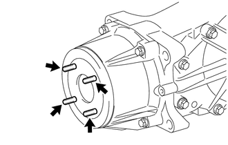
Using 2 nuts, remove the 4 stud bolts from the transmission coupling assembly.
41110H
3.REMOVE REAR DIFFERENTIAL FILLER PLUG
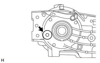
Using a 10 mm socket hexagon wrench, remove the rear differential filler plug and gasket.
41110D
4.REMOVE REAR DIFFERENTIAL DRAIN PLUG
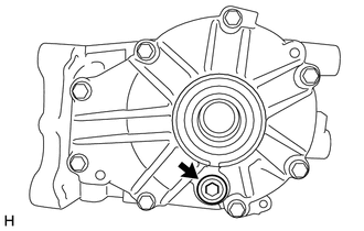
Using a 10 mm socket hexagon wrench, remove the rear differential drain plug and gasket.
41108A
5.REMOVE REAR DIFFERENTIAL CARRIER COVER PLUG
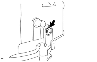
Using an 8 mm socket hexagon wrench, remove the rear differential carrier cover plug.
41108C
6.REMOVE REAR DIFFERENTIAL CARRIER COVER BREATHER PLUG
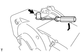
Using a chisel and hammer, slightly pry out the rear differential carrier cover breather plug.
Using a screwdriver, lightly pry up and remove the rear differential carrier cover breather plug.
7.INSPECT RUNOUT OF TRANSMISSION COUPLING ASSEMBLY
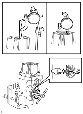
| *a | Vertical Runout |
| *b | Lateral Runout |
Attach a lever probe to a dial indicator and set the probe at a right angle to the inner surface of the transmission coupling assembly.
Using SST, rotate the transmission coupling assembly forward and in reverse and measure the vertical runout.
- SST
- 09564-32011
- Maximum:
0.06 mm (0.00236 in.)
- HINT:
-
If the measurement is more than the maximum, replace the transmission coupling assembly.
Set the dial indicator at a right angle to the transmission coupling assembly in the position shown in the illustration.
Using SST, rotate the transmission coupling assembly forward and in reverse and measure the lateral runout.
- SST
- 09564-32011
- Maximum:
0.07 mm (0.00276 in.)
- HINT:
-
If the measurement is more than the maximum, replace the transmission coupling assembly.
41330D
8.REMOVE TRANSMISSION COUPLING ASSEMBLY
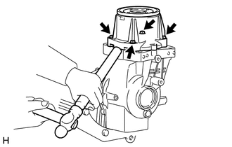
Remove the 4 bolts, and, using a brass bar and hammer, lightly tap the transmission coupling assembly to remove it from the rear differential carrier assembly.
- NOTICE:
- ·
Put the brass bar against the rib of the transmission coupling assembly.
·When removing the transmission coupling assembly, be careful not to scratch the installation surface.
- HINT:
-
To prevent the transmission coupling assembly from falling, leave 2 of the bolts screwed in by 5 or 6 threads.
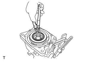
Using a snap ring expander, remove the snap ring.
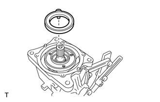
Remove the 4WD linear solenoid from the yoke.
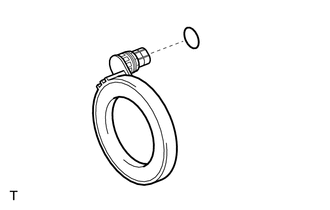
Remove the O-ring from the 4WD linear solenoid.
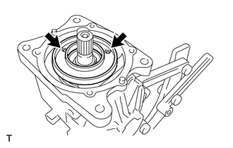
Using a 5 mm socket hexagon wrench, remove the 2 bolts and the yoke from the rear differential carrier sub-assembly.
41330E
9.REMOVE TRANSMISSION COUPLING CONICAL SPRING WASHER
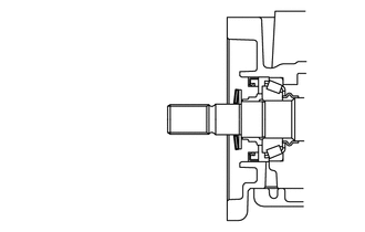
| *1 | Transmission Coupling Conical Spring Washer |
Remove the transmission coupling conical spring washer from the rear differential carrier sub-assembly.
41330J
10.REMOVE TRANSMISSION COUPLING SHIM
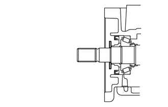
| *1 | Transmission Coupling Shim |
Remove the transmission coupling shim from the rear differential carrier sub-assembly.
11.INSPECT DIFFERENTIAL RING GEAR BACKLASH

| *a | Turn |
| *b | Hold |
Insert a dial indicator into the rear differential side gear shaft oil seal hole, and place it perpendicular to the edge of a ring gear tooth.
Using SST, secure the differential drive pinion.
- SST
- 09556-52010
Using SST, check the backlash while rotating the rear differential case sub-assembly forward and in reverse.
- SST
- 09564-32011
- Standard:
0.088 to 0.208 mm (0.00347 to 0.00818 in.)
- NOTICE:
-
Measure the ring gear at 3 or more locations.
12.INSPECT DIFFERENTIAL DRIVE PINION PRELOAD
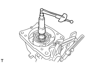
Using SST and a torque wrench, measure the preload (starting torque) of the backlash between the differential drive pinion and differential ring gear.
- SST
- 09556-52010
- Standard:
0.77 to 1.26 N*m (8 to 12 kgf*cm, 7 to 11 in.*lbf)
13.INSPECT TOTAL PRELOAD
Using SST and a torque wrench, measure the preload (at the start of torque) with the teeth of the drive pinion and differential ring gear in contact.
- SST
- 09556-52010
- Standard:
Total preload = drive pinion preload + 0.58 to 1.01 N*m (6 to 10 kgf*cm, 5 to 8 in.*lbf)
- NOTICE:
-
Measure the preload after rotating the case bearing several times in the forward and reverse directions to make sure the bearing is operating correctly.
42330G
14.REMOVE REAR DRIVE SHAFT OIL SEAL RH
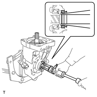
| *1 | Rear Drive Shaft Oil Seal RH |
Using SST, remove the rear drive shaft oil seal RH from the rear differential carrier sub-assembly.
- SST
- 09308-00010
42340D
15.REMOVE REAR DRIVE SHAFT OIL SEAL LH
- HINT:
-
Perform the same procedure as for the RH side.
16.REMOVE DIAPHRAGM OIL SEAL
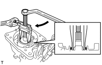
| *1 | Diaphragm Oil Seal |
| *a | Turn |
| *b | Hold |
Using SST, remove the diaphragm oil seal from the rear differential carrier sub-assembly.
- SST
- 09308-10010
41204B
17.REMOVE REAR DRIVE PINION NUT
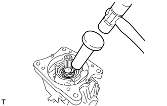
Using SST and a hammer, loosen the staked part of the rear drive pinion nut.
- SST
- 09930-00010
- NOTICE:
- ·
Use SST with the tapered surface facing the shaft side.
·Do not grind the end of SST with a grinder or other tool.
·Completely loosen the staked part of the rear drive pinion nut.
·Do not damage the threads of the differential drive pinion.
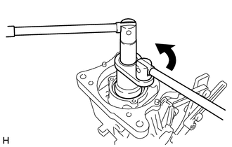
| *a | Turn |
| *b | Hold |
Using SST, secure the differential drive pinion and remove the rear drive pinion nut from the differential drive pinion.
- SST
- 09556-52010 09564-16020
41201B
18.REMOVE REAR DRIVE PINION FRONT BEARING
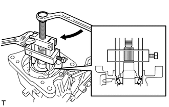
| *a | Turn |
| *b | Hold |
Using SST, remove the rear drive pinion front tapered roller bearing (inner race) from the rear differential carrier sub-assembly.
- SST
- 09556-30010
19.REMOVE DIFFERENTIAL SIDE BEARING RETAINER
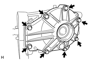
Remove the 8 bolts.
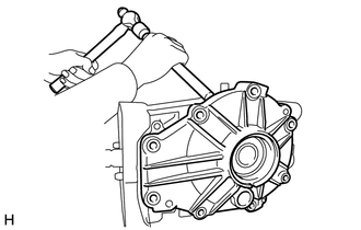
Using a brass bar and hammer, lightly tap the differential side bearing retainer and remove it.
- NOTICE:
- ·
Put the brass bar against the rib of the differential side bearing retainer.
·When removing the differential side bearing retainer, be careful not to scratch the installation surface.
- HINT:
-
Prevent the differential side bearing retainer from falling by screwing in 2 bolts by 5 or 6 threads.
41301
20.REMOVE REAR DIFFERENTIAL CASE SUB-ASSEMBLY
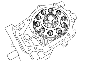
Remove the rear differential case sub-assembly from the rear differential carrier sub-assembly.
21.REMOVE DIFFERENTIAL DRIVE PINION
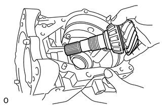
Remove the differential drive pinion from the rear differential carrier sub-assembly.
- NOTICE:
-
If either the rear differential drive pinion or the differential ring gear has been scratched, replace both.
41231
22.REMOVE REAR DIFFERENTIAL DRIVE PINION BEARING SPACER
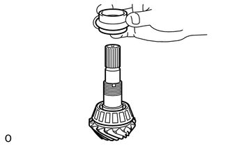
Remove the rear differential drive pinion bearing spacer from the differential drive pinion.
41201A
23.REMOVE REAR DRIVE PINION REAR BEARING
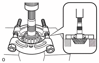
Using SST and a press, remove the rear drive pinion rear tapered roller bearing (inner race) from the differential drive pinion.
- SST
- 09950-00020
- NOTICE:
-
If the rear differential driver pinion or differential ring gear is damaged, replace them both.
Remove the rear differential drive pinion washer.
41201B
24.REMOVE REAR DRIVE PINION FRONT BEARING
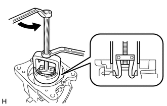
| *a | Turn |
| *b | Hold |
Attach the claws of SST to the rear drive pinion front tapered roller bearing (outer race) from the notches in the differential carrier sub-assembly.
- SST
- 09612-65014 (09612-01020, 09612-01050)
Using SST, remove the rear drive pinion front tapered roller bearing (outer race) from the rear differential carrier sub-assembly.
- SST
- 09612-65014 (09612-01020, 09612-01050)
41201A
25.REMOVE REAR DRIVE PINION REAR BEARING
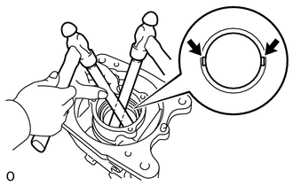
Using a brass bar and hammer, uniformly lightly tap the rear drive pinion rear tapered roller bearing (outer race) and remove it.
- NOTICE:
-
Put the brass bar into one of the notches.
41301A
26.REMOVE REAR DIFFERENTIAL CASE BEARING RH
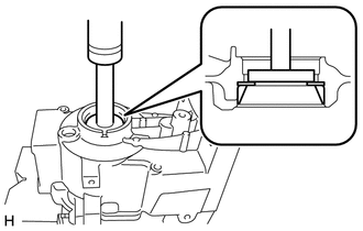
| *1 | Rear Differential Side Gear Shaft Washer |
| *2 | Rear Differential Case Bearing RH (Outer Race) |
Using SST and a press, remove the rear differential case bearing RH (outer race) and rear differential side gear shaft washer from the rear differential carrier sub-assembly.
- SST
- 09950-60011 (09951-00510)
09950-70010 (09951-07100)
41301A
27.REMOVE REAR DIFFERENTIAL CASE BEARING LH
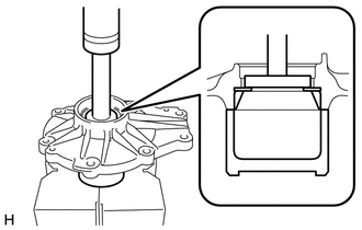
| *1 | Rear Differential Side Gear Shaft Washer |
| *2 | Rear Differential Case Bearing LH (Outer Race) |
Using SST and a press, remove the rear differential case bearing LH (outer race) and rear differential side gear shaft washer from the differential side bearing retainer.
- SST
- 09950-60011 (09951-00460)
09950-70010 (09951-07100)
09649-17010
41301A
28.REMOVE REAR DIFFERENTIAL CASE BEARING RH
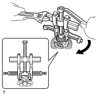
| *a | Turn |
| *b | Hold |
Using SST, remove the rear differential case bearing RH (inner race) from the rear differential case sub-assembly.
- SST
- 09950-40011 (09951-04010, 09952-04010, 09953-04020, 09954-04010, 09955-04061, 09957-04010, 09958-04011)
09950-60011 (09951-00320)
- NOTICE:
-
Before using SST center bolt (09953-04020), apply oil to its threads and tip.
- HINT:
- ·
If the race remains on the rear differential case sub-assembly, repeat the step above to remove the rear differential case bearing RH (inner race).
·If the rear differential case bearing RH (inner race) is deformed, replace it with a new one.
41301A
29.REMOVE REAR DIFFERENTIAL CASE BEARING LH
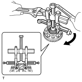
| *a | Turn |
| *b | Hold |
Using SST, remove the rear differential case bearing LH (inner race) from the rear differential case sub-assembly.
- SST
- 09950-40011 (09951-04010, 09952-04010, 09953-04020, 09954-04010, 09955-04071, 09957-04010, 09958-04011)
09950-60011 (09951-00320)
- NOTICE:
-
Before using SST center bolt (09953-04020), apply oil to its threads and tip.
- HINT:
- ·
If the race remains on the rear differential case sub-assembly, repeat the step above to remove the rear differential case bearing LH (inner race).
·If the rear differential case bearing LH (inner race) is deformed, replace it with a new one.
30.REMOVE DIFFERENTIAL RING GEAR
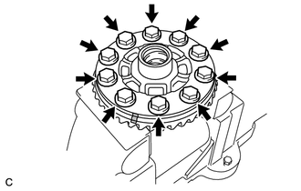
| *a | Matchmark |
Mount the rear differential case sub-assembly in a vise between aluminum plates.
- NOTICE:
-
Do not overtighten the vise.
Put matchmarks on the rear differential case sub-assembly and differential ring gear.
Remove the 10 rear differential case bolts.
Using a plastic-faced hammer, lightly tap the periphery of the differential ring gear to remove it from the rear differential case sub-assembly.
- HINT:
-
Place a cloth on the teeth side of the ring gear to prevent damage.
41183
31.REMOVE REAR DIFFERENTIAL BREATHER PLUG OIL DEFLECTOR
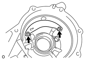
Using a 5 mm socket hexagon wrench, remove the 2 bolts and rear differential breather plug oil deflector.
32.REMOVE STRAIGHT PIN
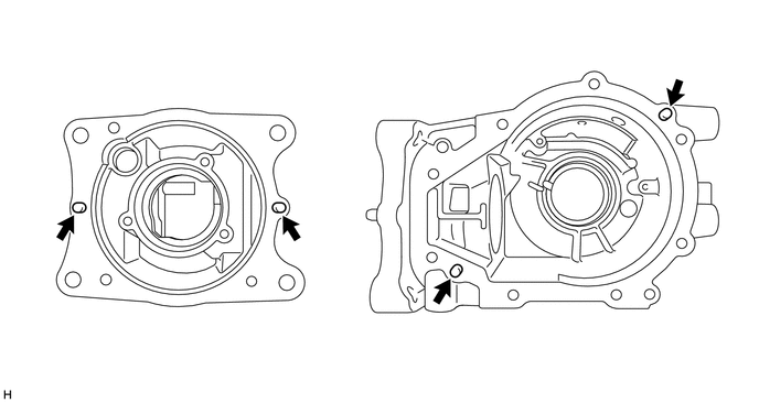
Remove the 4 straight pins from the rear differential carrier sub-assembly.