INTERIOR PANELS / TRIM INSTRUMENT PANEL SAFETY PAD REASSEMBLY
PROCEDURE

 55356C
1.INSTALL NO. 2 INSTRUMENT PANEL CUSHION
55356C
1.INSTALL NO. 2 INSTRUMENT PANEL CUSHION
Clean the instrument panel safety pad sub-assembly surface.
Remove any remaining double-sided tape from the instrument panel safety pad sub-assembly.
Wipe off any tape adhesive residue with cleaner.
Remove the release paper from a new No. 2 instrument panel cushion.
- HINT:
-
After removing the release paper, keep the exposed adhesive free from foreign matter.
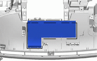
| *a | Line |
Install the No. 2 instrument panel cushion as shown in the illustration.
- HINT:
-
Install the No. 2 instrument panel cushion within the line on the instrument panel safety pad sub-assembly.
55349A
2.INSTALL INSTRUMENT PANEL CUSHION
Clean the instrument panel safety pad sub-assembly surface.
Remove any remaining double-sided tape from the instrument panel safety pad sub-assembly surface.
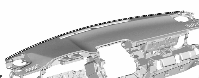

|
Cleaning Area | - | - |
Wipe off any tape adhesive residue with cleaner.
Remove the release paper from a new instrument panel cushion.
- HINT:
-
After removing the release paper, keep the exposed adhesive free from foreign matter.
Install the instrument panel cushion as shown in the illustration.
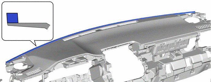
| *a | Edge of Curved Surface | *b | Outline |
55328
3.INSTALL NO. 1 INSTRUMENT PANEL PIN
Engage the 2 guides.
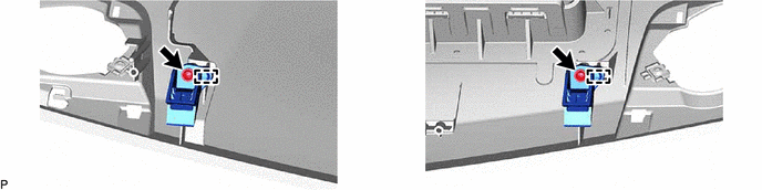
Install the 2 No. 1 instrument panel pins with the 2 screws <C>.
73960A
4.INSTALL INSTRUMENT PANEL PASSENGER AIRBAG ASSEMBLY
82142A
5.INSTALL NO. 2 INSTRUMENT PANEL WIRE
6.INSTALL NAVIGATION ANTENNA ASSEMBLY WITH BRACKET
86101
7.INSTALL ANTENNA CORD SUB-ASSEMBLY
55972C
8.INSTALL NO. 2 SIDE DEFROSTER NOZZLE DUCT
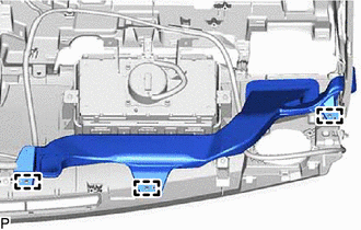
Engage the 3 guides.
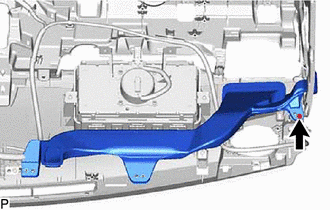
Install the No. 2 side defroster nozzle duct with the screw <C>.
88051A
9.INSTALL ION GENERATOR SUB-ASSEMBLY (w/ Ion Generator)
87201N
10.INSTALL AIR DUCT SUB-ASSEMBLY (w/ Ion Generator)
55086
11.INSTALL NO. 3 HEATER TO REGISTER DUCT SUB-ASSEMBLY
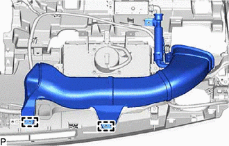
Engage the 2 guides.
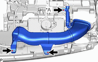
| *A | w/ Ion Generator |
Install the No. 3 heater to register duct sub-assembly with each screw <C>.
55971C
12.INSTALL NO. 1 SIDE DEFROSTER NOZZLE DUCT
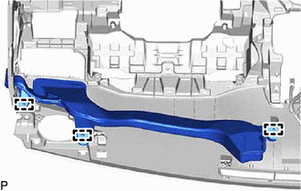
Engage the 3 guides.
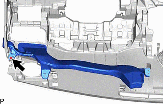
Install the No. 1 side defroster nozzle duct with the screw <C>.
55084E
13.INSTALL NO. 1 HEATER TO REGISTER DUCT SUB-ASSEMBLY
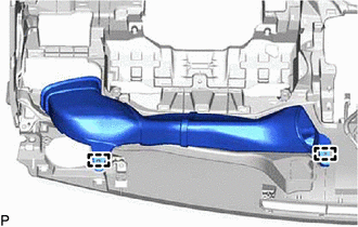
Engage the 2 guides.
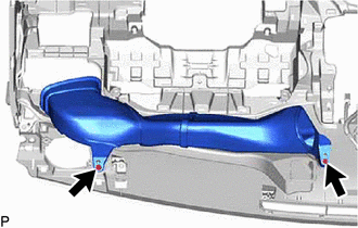
Install the No. 1 heater to register duct sub-assembly with the 2 screws <C>.
55950G
14.INSTALL DEFROSTER NOZZLE ASSEMBLY
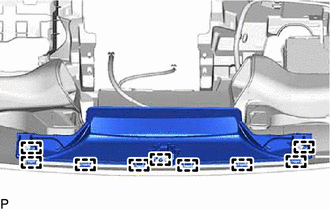
Engage the 9 guides.
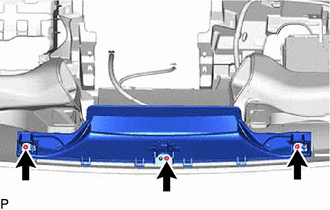
Install the defroster nozzle assembly with the 3 screws <C>.
55670A
15.INSTALL CENTER INSTRUMENT PANEL REGISTER ASSEMBLY
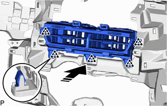

|
Install in this Direction |
Engage the 5 clips as shown in the illustration to install the center instrument panel register assembly.
55650
16.INSTALL NO. 1 INSTRUMENT PANEL REGISTER ASSEMBLY
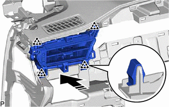
|
|
Install in this Direction |
Engage the 4 clips as shown in the illustration to install the No. 1 instrument panel register assembly.
55660
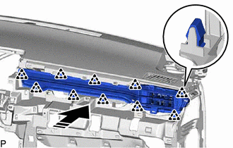
17.INSTALL NO. 2 INSTRUMENT PANEL REGISTER ASSEMBLY
|
|
Install in this Direction |
Engage the 10 clips as shown in the illustration to install the No. 2 instrument panel register assembly.
55011A
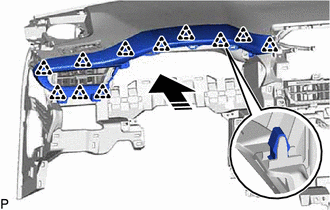
18.INSTALL NO. 1 INSTRUMENT PANEL GARNISH SUB-ASSEMBLY
|
|
Install in this Direction |
Engage the 11 clips as shown in the illustration to install the No. 1 instrument panel garnish sub-assembly.
55012A
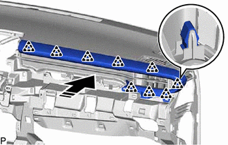
19.INSTALL NO. 2 INSTRUMENT PANEL GARNISH SUB-ASSEMBLY
|
|
Install in this Direction |
Engage the 9 clips as shown in the illustration to install the No. 2 instrument panel garnish sub-assembly.
55548A
20.INSTALL INSTRUMENT PANEL HOLE COVER (w/ Headup Display)

|
|
Install in this Direction |
Engage the 2 guides and 5 claws as shown in the illustration to install the instrument panel hole cover.