INTERIOR PANELS / TRIM ROOF HEADLINING REASSEMBLY
PROCEDURE

 86101J
1.INSTALL NO. 2 ANTENNA CORD SUB-ASSEMBLY
86101J
1.INSTALL NO. 2 ANTENNA CORD SUB-ASSEMBLY
for Short Type Panoramic Fixed Moon Roof:
for Long Type Panoramic Fixed Moon Roof:
82171
2.INSTALL NO. 1 ROOF WIRE (for Short Type Panoramic Fixed Moon Roof)
Apply butyl tape as shown in the illustration.
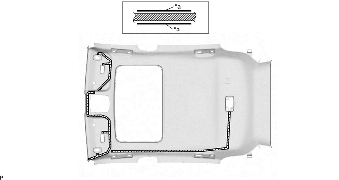
| *a | Marking | - | - |

|
Butyl tape | - | - |
- NOTICE:
-
Securely attach the butyl tape.
Turn the 2 visor connectors clockwise approximately 90° to install them to the roof headlining assembly.
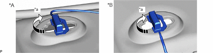
| *A | for LH side | *B | for RH side |
| *a | 90° | - | - |

|
Rotation Direction | - | - |
Align the marking tape on the No. 1 roof wire with the roof headlining assembly as shown in the illustration.
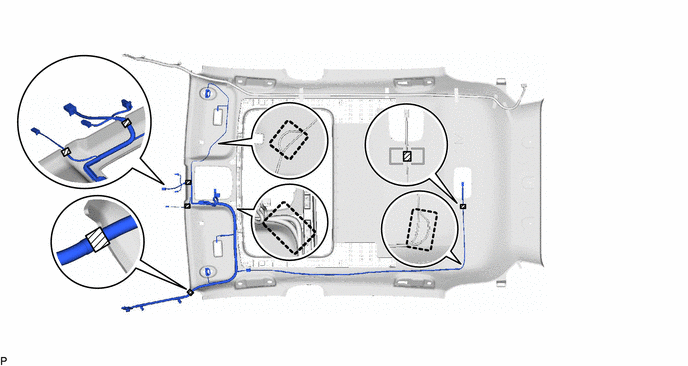
|
|
Marking Tape | - | - |

|
Adjustment Area | - | - |
Attach the No. 1 roof wire with the butyl tape.
- NOTICE:
- ·
Securely attach the No. 1 roof wire.
·If any of the No. 1 roof wire is left loose, it will cause an abnormal noise.
·Make sure to attach the No. 1 roof wire without leaving any of it loose.
- HINT:
-
Secure the extra length of the No. 1 roof wire in the adjustment area.
Install the No. 1 roof wire to the roof headlining assembly with adhesive tape.
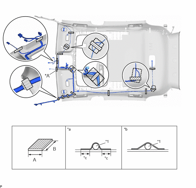
| *A | w/ ETC | - | - |
| *1 | No. 1 Roof Wire | - | - |
| *a | Correct | *b | Incorrect |
| *c | 10 mm (0.394 in.) or more | - | - |
|
|
Adhesive Tape | - | - |
|
|
Adjustment Area | - | - |
| Area | Dimension | Area | Dimension |
|---|---|---|---|
| A | 20 mm (0.787 in.) | B | 80 mm (3.15 in.) or more |
- NOTICE:
- ·
Apply the tape securely in place.
·Do not touch the adhesive surface when applying the tape to prevent adhesion failure.
82171
3.INSTALL NO. 1 ROOF WIRE (for Long Type Panoramic Fixed Moon Roof)
Apply butyl tape as shown in the illustration.
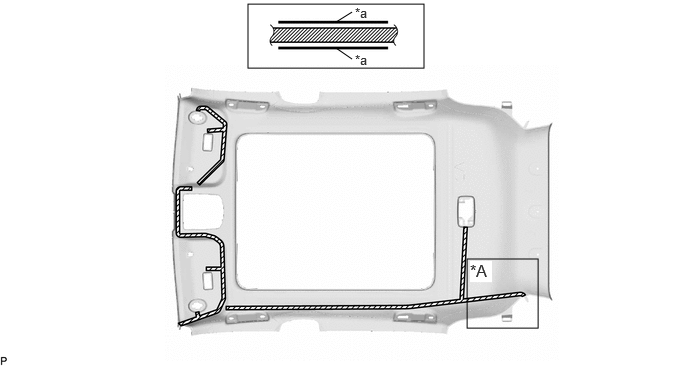
| *A | w/ Digital Inner Mirror | - | - |
| *a | Marking | - | - |
|
|
Butyl tape | - | - |
- NOTICE:
-
Securely attach the butyl tape.
Turn the 2 visor connectors clockwise approximately 90° to install them to the roof headlining assembly.
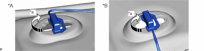
| *A | for LH side | *B | for RH side |
| *a | 90° | - | - |
|
|
Rotation Direction | - | - |
Align the marking tape on the No. 1 roof wire with the roof headlining assembly as shown in the illustration.
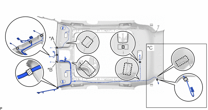
| *A | w/ Rain Sensor | *B | w/ ETC |
| *C | w/ Digital Inner Mirror | - | - |
|
|
Marking Tape | - | - |
|
|
Adjustment Area | - | - |
Attach the No. 1 roof wire with the butyl tape.
- NOTICE:
- ·
Securely attach the No. 1 roof wire.
·If any of the No. 1 roof wire is left loose, it will cause an abnormal noise.
·Make sure to attach the No. 1 roof wire without leaving any of it loose.
- HINT:
-
Secure the extra length of the No. 1 roof wire in the adjustment area.
Install the No. 1 roof wire to the roof headlining assembly with adhesive tape.

| *A | w/ Rain Sensor | *B | w/ ETC |
| *C | w/ Digital Inner Mirror | - | - |
| *1 | No. 1 Roof Wire | - | - |
| *a | Correct | *b | Incorrect |
| *c | 10 mm (0.394 in.) or more | - | - |
|
|
Adhesive Tape | - | - |
|
|
Adjustment Area | - | - |
| Area | Dimension | Area | Dimension |
|---|---|---|---|
| A | 20 mm (0.787 in.) | B | 80 mm (3.15 in.) or more |
- NOTICE:
- ·
Apply the tape securely in place.
·Do not touch the adhesive surface when applying the tape to prevent adhesion failure.
63353C
4.INSTALL CENTER ROOF HEADLINING PAD (for Long Type Panoramic Fixed Moon Roof)
for GTMC Made:
Remove the release paper from new center roof headlining pad.
- HINT:
-
After removing the release paper, keep the exposed adhesive free from foreign matter.
Align the center roof headlining pad with the marking on the roof headlining assembly and install it as shown in the illustration.
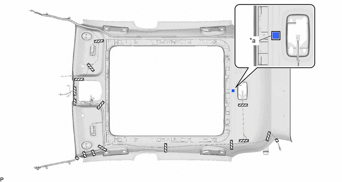
| *a | Marking | - | - |
63356B
5.INSTALL FRONT SIDE ROOF HEADLINING PAD
Remove the release paper from 2 new front side roof headlining pads.
- HINT:
-
After removing the release paper, keep the exposed adhesive free from foreign matter.
Align the 2 front side roof headlining pads with the markings on the roof headlining assembly and install them as shown in the illustration.
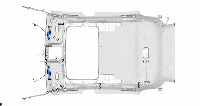
| *a | Marking | - | - |
63356B
6.INSTALL ROOF HEADLINING PAD LH
Align a roof headlining pad LH with the marking on the roof headlining assembly and install it using hot-melt glue as shown in the illustration.
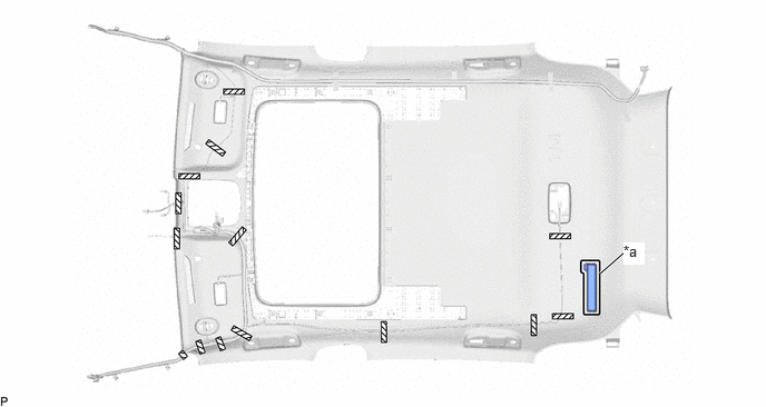
| *a | Marking | - | - |
- HINT:
-
Make sure to install the roof headlining pad LH firmly to prevent it from being peeled off when installing the roof headlining assembly.
63355C
7.INSTALL ROOF HEADLINING PAD RH
- HINT:
-
Use the same procedure as for the LH side.