EXTERIOR PANELS / TRIM REAR BUMPER REASSEMBLY
PROCEDURE

 52171C
1.INSTALL REAR BUMPER REINFORCEMENT
52171C
1.INSTALL REAR BUMPER REINFORCEMENT
- HINT:
-
Perform this procedure only when replacement of the rear bumper reinforcement is necessary.
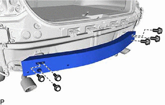
Install the rear bumper reinforcement with the 6 bolts.
- Torque:
- 20 N*m (204 kgf*cm, 15 ft.*lbf)
52188A
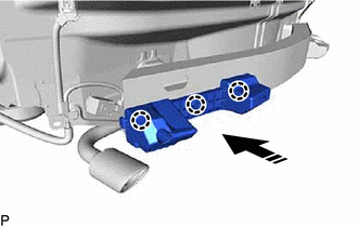
2.INSTALL REAR BUMPER ARM REINFORCEMENT LH
- HINT:
-
Perform this procedure only when replacement of the rear bumper arm reinforcement LH is necessary.

|
Install in this Direction |
Engage the 3 claws as shown in the illustration to install the rear bumper arm reinforcement LH.
52187A
3.INSTALL REAR BUMPER ARM REINFORCEMENT RH
- HINT:
-
Use the same procedure as for the LH side.
52156A
4.INSTALL REAR BUMPER SIDE SUPPORT LH
- HINT:
-
Perform this procedure only when replacement of the rear bumper side support LH is necessary.
for SFTM Made:
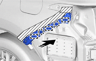
Engage the 3 guides and 2 claws as shown in the illustration.
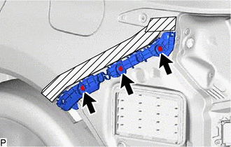
Install the rear bumper side support LH with the 3 screws.
for GTMC Made:
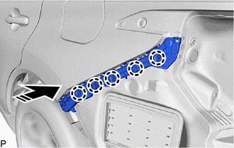
|
|
Install in this Direction |
Engage the 5 claws as shown in the illustration.
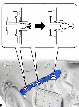
Engage the 3 clips as shown in the illustration to install the rear bumper side support LH.
52155A
5.INSTALL REAR BUMPER SIDE SUPPORT RH
- HINT:
-
Use the same procedure as for the LH side.
52563D
6.INSTALL REAR BUMPER UPPER RETAINER LH
- HINT:
-
Perform this procedure only when replacement of the rear bumper upper retainer LH is necessary.
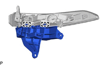
Engage the 2 guides to install the rear bumper upper retainer LH to the rear combination light assembly LH.
52562E
7.INSTALL REAR BUMPER UPPER RETAINER RH
- HINT:
-
Use the same procedure as for the LH side.
8.INSTALL REAR COMBINATION LIGHT ASSEMBLY WITH RETAINER LH
- HINT:
- ·
Perform this procedure only when replacement of the rear bumper upper retainer LH is necessary.
·Use the same procedure for the RH side and LH side.
9.INSTALL REAR COMBINATION LIGHT ASSEMBLY WITH RETAINER RH
- HINT:
-
Use the same procedure as for the LH side.
52592
10.INSTALL REAR BUMPER SIDE SEAL LH
- HINT:
-
Perform this procedure only when replacement of the rear bumper side seal LH is necessary.
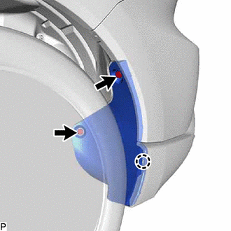
Engage the claw.
Install the rear bumper side seal LH with the 2 clips.
52591
11.INSTALL REAR BUMPER SIDE SEAL RH
- HINT:
-
Perform this procedure only when replacement of the rear bumper side seal RH is necessary.
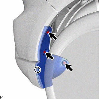
Engage the claw.
Install the rear bumper side seal RH with the 3 clips.
52151G
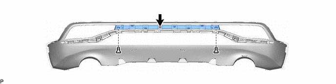
12.INSTALL REAR BUMPER EXTENSION (for GTMC Made)
Engage the 2 guides and 5 claws.
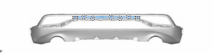
Install the rear bumper extension with the 2 clips and screws.
52751
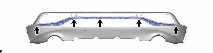
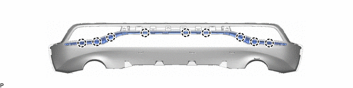
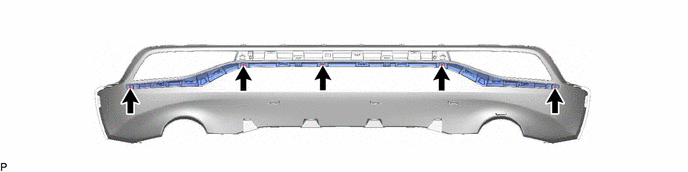
13.INSTALL REAR BUMPER MOULDING
for SFTM Made:
Engage the 9 claws.
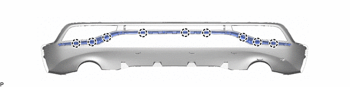
Install the rear bumper moulding with the 5 screws.
for GTMC Made:
Engage the 9 claws.
Install the rear bumper moulding with the 5 screws.
52169C
14.INSTALL REAR BUMPER LOWER COVER
for SFTM Made:
Engage the 2 guides and 12 claws.
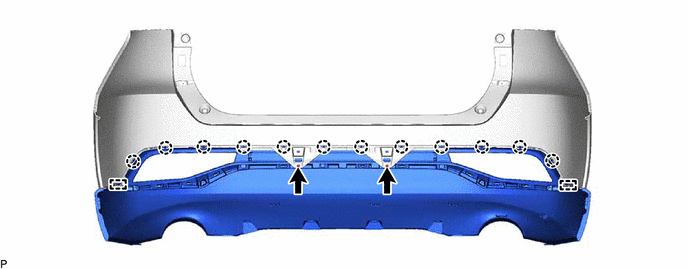
Install the 2 screws.
Install the rear bumper lower cover to the rear bumper cover with the 6 clips.
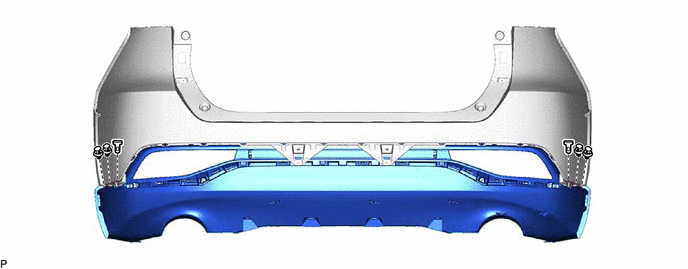
for GTMC Made:
Engage the 2 guides and 12 claws.
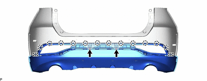
Install the 2 screws.
Install the rear bumper lower cover to the rear bumper cover with the 6 clips.
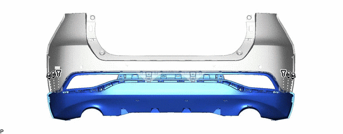
52462B
15.INSTALL REAR BUMPER PAD
- HINT:
-
When installing the rear bumper pad, heat the rear bumper cover using a heat light.
- Heating Temperature:
Item Temperature Rear Bumper Cover 20 to 30 °C (68 to 86 °F)
- CAUTION:
-
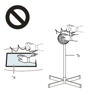 2.365,2 2.698,2 false 0.5,2.333 0.5,2.667 true 0.427,2.708 0.74,2.865 0.313,0.156 10 false *a 2.76,1.927 3.073,2.083 0.313,0.156 10 false *b
*a Heated Part *b Heat Light
- ·
Do not touch the heat light and heated parts, touching the heat light may result in burns.
·Touching heated parts for a long time may result in burns.
- NOTICE:
-
Do not heat the rear bumper cover excessively.
Clean the rear bumper cover surface.
Using a heat light, heat the rear bumper cover surface.
Remove any double-sided tape from the rear bumper cover.
Wipe off any tape adhesive residue with cleaner.
Install a new rear bumper pad.
Using a heat light, heat the rear bumper cover surface.
Remove the release paper from the rear bumper pad.
- HINT:
-
After removing the release paper, keep the exposed adhesive free from foreign matter.
Install the 2 rear bumper pads as shown in the illustration.
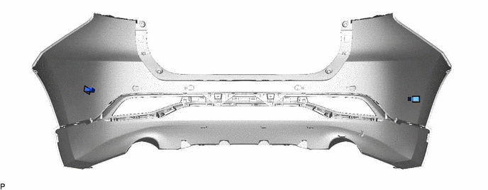
| *a | Line | - | - |
- HINT:
- ·
Install the rear bumper pad along the line on the rear bumper cover.
·Press the rear bumper pad firmly to install it.
16.INSTALL ULTRASONIC SENSOR CLIP
- HINT:
-
When installing the ultrasonic sensor clip, heat the rear bumper cover using a heat light.
- Heating Temperature:
Item Temperature Rear Bumper Cover 20 to 30 °C (68 to 86 °F)
- CAUTION:
-
2.365,2 2.698,2 false 0.5,2.333 0.5,2.667 true 0.427,2.708 0.74,2.865 0.313,0.156 10 false *a 2.76,1.927 3.073,2.083 0.313,0.156 10 false *b
*a Heated Part *b Heat Light
- ·
Do not touch the heat light and heated parts, touching the heat light may result in burns.
·Touching heated parts for a long time may result in burns.
- NOTICE:
-
Do not heat the rear bumper cover excessively.
Clean the rear bumper cover surface.
Using a heat light, heat the rear bumper cover surface.
Remove any double-sided tape from the rear bumper cover.
Wipe off any tape adhesive residue with cleaner.
Install a new ultrasonic sensor clip.
Using a heat light, heat the rear bumper cover surface.
Remove the release paper from the ultrasonic sensor clip.
- HINT:
-
After removing the release paper, keep the exposed adhesive free from foreign matter.
Install the ultrasonic sensor clip as shown in the illustration.
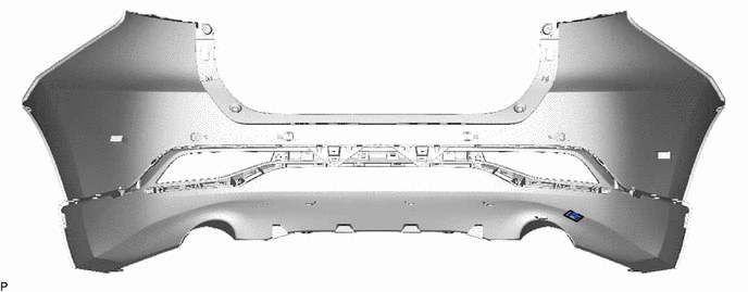
| *a | Line | - | - |
- HINT:
- ·
Install the rear bumper pad along the line on the rear bumper cover.
·Press the rear bumper pad firmly to install it.
82182
17.INSTALL NO. 2 LUGGAGE ROOM WIRE
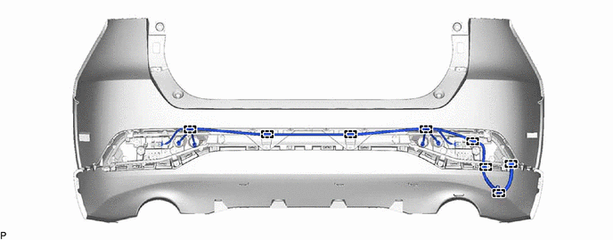
for SFTM Made:
Engage each clamp to install the No. 2 luggage room wire.
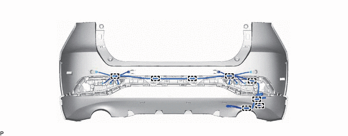
for GTMC Made:
Engage each clamp to install the No. 2 luggage room wire.
18.INSTALL REAR TURN SIGNAL LIGHT ASSEMBLY LH
19.INSTALL REAR TURN SIGNAL LIGHT ASSEMBLY RH
- HINT:
-
Use the same procedure as for the LH side.
89C48A
20.INSTALL REAR CORNER ULTRASONIC SENSOR RETAINER (w/ TOYOTA Parking Assist-sensor System)
89C48B
21.INSTALL REAR CENTER ULTRASONIC SENSOR RETAINER (w/ TOYOTA Parking Assist-sensor System)
89342
22.INSTALL REAR CORNER ULTRASONIC SENSOR (w/ TOYOTA Parking Assist-sensor System)
89342A
23.INSTALL REAR CENTER ULTRASONIC SENSOR (w/ TOYOTA Parking Assist-sensor System)
891B0
24.INSTALL KICK DOOR CONTROL SENSOR ASSEMBLY (w/ Kick Sensor)