GF1A TRANSFER / 4WD / AWD TRANSFER ASSEMBLY REASSEMBLY
CAUTION / NOTICE / HINT
- NOTICE:
-
Steps 9 to 16 are temporary reassembly procedures for adjustment purposes.
PROCEDURE

 36128B
1.INSTALL BREATHER OIL DEFLECTOR
36128B
1.INSTALL BREATHER OIL DEFLECTOR
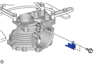
Install a new breather oil deflector to the transfer case with the 2 bolts.
- Torque:
- 6.5 N*m (66 kgf*cm, 58 in.*lbf)
41319
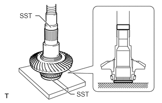
2.INSTALL TRANSFER RING GEAR MOUNTING CASE
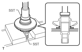
Using SST and a press, press the transfer ring gear mounting case into the transfer ring gear.
- SST
- 09316-12010
09950-60011 (09951-00560)
- NOTICE:
-
Do not put stress on the teeth of the transfer ring gear.
36212L
3.INSTALL SHAFT SNAP RING
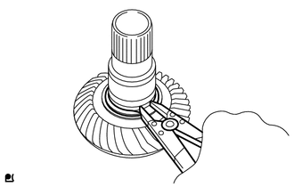
Using a snap ring expander, install a new shaft snap ring.
41301H
4.INSTALL RING GEAR MOUNTING CASE BEARING RH
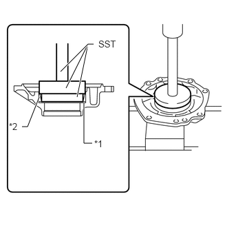
| *1 | No. 2 Transfer Ring Gear Mounting Case Washer |
| *2 | Ring Gear Mounting Case Bearing RH (Outer Race) |
Install a new No. 2 transfer ring gear mounting case washer to the No. 1 transfer case cover.
- HINT:
-
Install a No. 2 transfer ring gear mounting case washer with the same thickness as the one before the disassembly.
Using SST and a press, press the ring gear mounting case bearing RH (outer race) into the No. 1 transfer case cover.
- SST
- 09950-60021 (09951-00750, 09952-06010)
09950-70010 (09951-07150)
09951-00850
- NOTICE:
- ·
Press in the ring gear mounting case bearing RH (outer race) and No. 2 transfer ring gear mounting case washer until they fit to the edge.
·Do not put stress on the rolling contact surface of the ring gear mounting case bearing RH (outer race).
Using SST and a press, press the ring gear mounting case bearing RH (inner race) into the transfer ring gear mounting case.
- SST
- 09950-60011 (09951-00440, 09951-00650)
- NOTICE:
-
Do not deform the ring gear mounting case bearing RH (inner race) cage.
- HINT:
-
When reusing the ring gear mounting case bearing RH, coat the ring gear mounting case bearing RH with Toyota genuine differential gear oil LT, LX or equivalent.
41301H
5.INSTALL RING GEAR MOUNTING CASE BEARING LH
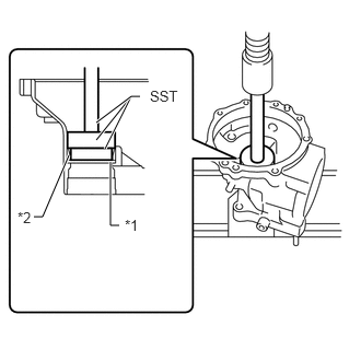
| *1 | No. 1 Ring Gear Mounting Case Washer |
| *2 | Ring Gear Mounting Case Bearing LH (Outer Race) |
Install a new No. 1 ring gear mounting case washer to the transfer case.
- HINT:
-
Install a No. 1 ring gear mounting case washer with the same thickness as the one before the disassembly.
Using SST and a press, press the ring gear mounting case bearing LH (outer race) into the transfer case.
- SST
- 09950-60011 (09951-00570, 09951-00650, 09952-06010)
09950-70010 (09951-07150)
- NOTICE:
- ·
Press in the ring gear mounting case bearing LH (outer race) and No. 1 ring gear mounting case washer until they fit to the edge.
·Do not put stress on the rolling contact surface of the ring gear mounting case bearing LH (outer race).
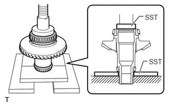
Using SST and a press, press the ring gear mounting case bearing LH (inner race) into the transfer ring gear mounting case.
- SST
- 09336-16010
09950-60011 (09951-00560)
- NOTICE:
-
Do not deform the ring gear mounting case bearing LH (inner race) cage.
- HINT:
-
When reusing the ring gear mounting case bearing LH, coat the ring gear mounting case bearing LH with Toyota genuine differential gear oil LT, LX or equivalent.
36275E
6.INSTALL TRANSFER OUTPUT SHAFT WASHER
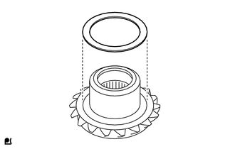
Install the transfer output shaft washer to the transfer driven pinion.
41201K
7.INSTALL FRONT TRANSFER DRIVEN PINION BEARING
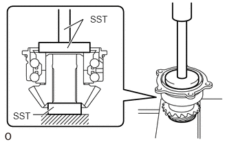
Using SST and a press, press the front transfer driven pinion bearing into the transfer driven pinion.
- SST
- 09950-60011 (09951-00440)
09950-60021 (09951-00750)
09950-70010 (09951-07150)
- NOTICE:
-
Do not apply stress to any parts of the front transfer driven pinion bearing inner race or transfer driven pinion other than the flat surfaces.
33325A
8.INSTALL REAR TRANSFER OUTPUT SHAFT DUST DEFLECTOR
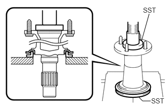
Using SST and a press, press a new rear transfer output shaft dust deflector into the rear transfer output shaft sub-assembly.
- SST
- 09316-12010
09950-60021 (09951-00680)
- NOTICE:
-
The rear transfer output shaft dust deflector should be installed completely.
9.INSTALL TRANSFER DRIVEN PINION
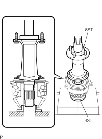
Using SST and a press, press the rear transfer output shaft sub-assembly into the transfer driven pinion.
- SST
- 09506-30012
09950-60021 (09951-00680)
- NOTICE:
-
Do not apply stress to any parts of the transfer output shaft flange or transfer driven pinion other than the flat surfaces.
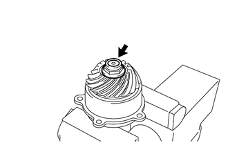
Secure the rear transfer output shaft sub-assembly in a vise between aluminum plates.
- NOTICE:
-
Do not overtighten the vise.
Using a 30 mm socket wrench, install a new transfer gear nut to the rear transfer output shaft sub-assembly.
- Torque:
- 360 N*m (3671 kgf*cm, 266 ft.*lbf)
36202
10.INSTALL REAR TRANSFER OUTPUT SHAFT SUB-ASSEMBLY
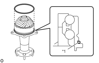
| *1 | O-ring |
Install a new O-ring to the front transfer driven pinion bearing.
- NOTICE:
- ·
Do not damage, deform or crack the O-ring.
·Firmly install the O-ring into the groove of the front transfer driven pinion bearing.
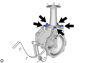
Install the rear transfer output shaft sub-assembly to the transfer case with the 5 bolts.
- Torque:
- 38 N*m (387 kgf*cm, 28 ft.*lbf)
- NOTICE:
-
Do not damage, deform or crack the O-ring.
11.INSPECT DRIVEN PINION PRELOAD
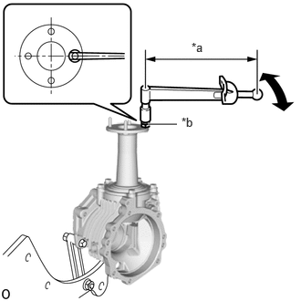
| *a | Torque Wrench Fulcrum Length |
| *b | Double Nut |
Install the double nut to the rear transfer output shaft sub-assembly stud bolt and set the torque wrench into place.
- HINT:
-
Adjust the double nut until the torque wrench is straight.
Using a torque wrench, check the total preload (starting torque) with the teeth of the drive pinion and ring gear in contact.
- Preload (at Starting):
Item Driven Pinion Preload New bearing
(with anti-rust oil)0.39 to 2.21 N*m (3.98 to 22.53 kgf*cm, 3.46 to 19.55 in.*lbf) Reused bearing
(when coated with gear oil)0.39 to 2.21 N*m (3.98 to 22.53 kgf*cm, 3.46 to 19.55 in.*lbf)
- NOTICE:
-
Measure the preload after rotating the bearing several times in the forward and backward directions to make sure the bearing is operating correctly.
- HINT:
- ·
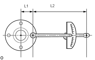 0.875,0.135 1.094,0.323 0.219,0.188 10 false L1 1.823,0.125 2.042,0.313 0.219,0.188 10 false L2
When using a torque wrench after changing its effective length, determine the reading of the torque wrench.
Formula T'=T x L2/(L1+L2) T' Reading of torque wrench (N*m (kgf*cm, ft.*lbf)) T Driven pinion preload (N*m (kgf*cm, ft.*lbf)) L1 Distance from center of rear transfer output shaft sub-assembly to center of stud bolt (cm (in.)) L2 Length of torque wrench (cm (in.))
·Distance from center of rear transfer output shaft sub-assembly to center of stud bolt (effective length of 38.9 mm (1.53 in.)) when using a torque wrench (effective length of 160 mm (6.30 in.)): 0.32 to 1.77 N*m (4 to 18 kgf*cm, 3 to 15 in.*lbf)
12.INSTALL TRANSFER RING GEAR
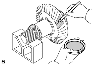
Uniformly apply a light coat of Prussian Blue on both sides of the transfer ring gear teeth.
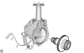
Install the transfer ring gear to the transfer case.
36121
13.INSTALL NO. 1 TRANSFER CASE COVER
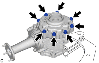
Install the No. 1 transfer case cover to the transfer case with the 8 bolts.
- Torque:
- 47 N*m (479 kgf*cm, 35 ft.*lbf)
14.ADJUST RING GEAR BACKLASH
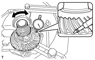
Insert a dial indicator into the transfer filler plug hole, and place it perpendicular to the edge of a transfer ring gear tooth.
While securing the rear transfer output shaft sub-assembly by hand, rotate the transfer ring gear mounting case forward and backward by hand and measure the backlash of the transfer ring gear and transfer driven pinion.
- Standard Backlash:
0.10 to 0.20 mm (0.00394 to 0.00787 in.)
- NOTICE:
-
Measure the ring gear at 3 or more locations.
If the result is not within the specified range, select a No. 1 ring gear mounting case washer (for backlash adjustment) and a No. 2 transfer ring gear mounting case washer (for preload adjustment) from the table below and reinstall them to bring the result within the specified range.
- HINT:
Insufficient Backlash Excessive Backlash No. 1 ring gear mounting case washer
(for backlash adjustment)Increase thickness Decrease thickness No. 2 transfer ring gear mounting case washer
(for preload adjustment)Decrease thickness Increase thickness
- No. 1 Ring Gear Mounting Case Washer (for backlash adjustment):
Part No. Thickness Identifying Mark Part No. Thickness Identifying Mark 36265-42010 1.97 mm (0.0776 in.) A0 36265-42210 2.37 mm (0.0933 in.) C0 36265-42020 1.99 mm (0.0783 in.) A1 36265-42220 2.39 mm (0.0941 in.) C1 36265-42030 2.01 mm (0.0791 in.) A2 36265-42230 2.41 mm (0.0949 in.) C2 36265-42040 2.03 mm (0.0799 in.) A3 36265-42240 2.43 mm (0.0957 in.) C3 36265-42050 2.05 mm (0.0807 in.) A4 36265-42250 2.45 mm (0.0965 in.) C4 36265-42060 2.07 mm (0.0815 in.) A5 36265-42260 2.47 mm (0.0972 in.) C5 36265-42070 2.09 mm (0.0823 in.) A6 36265-42270 2.49 mm (0.0980 in.) C6 36265-42080 2.11 mm (0.0831 in.) A7 36265-42280 2.51 mm (0.0988 in.) C7 36265-42090 2.13 mm (0.0839 in.) A8 36265-42290 2.53 mm (0.0996 in.) C8 36265-42100 2.15 mm (0.0846 in.) A9 36265-42300 2.55 mm (0.1004 in.) C9 36265-42110 2.17 mm (0.0854 in.) B0 36265-42310 2.57 mm (0.1012 in.) D0 36265-42120 2.19 mm (0.0862 in.) B1 36265-42320 2.59 mm (0.1020 in.) D1 36265-42130 2.21 mm (0.0870 in.) B2 36265-42330 2.61 mm (0.1028 in.) D2 36265-42140 2.23 mm (0.0878 in.) B3 36265-42340 2.63 mm (0.1035 in.) D3 36265-42150 2.25 mm (0.0886 in.) B4 36265-42350 2.65 mm (0.1043 in.) D4 36265-42160 2.27 mm (0.0894 in.) B5 36265-42360 2.67 mm (0.1051 in.) D5 36265-42170 2.29 mm (0.0902 in.) B6 36265-42370 2.69 mm (0.1059 in.) D6 36265-42180 2.31 mm (0.0909 in.) B7 36265-42380 2.71 mm (0.1067 in.) D7 36265-42190 2.33 mm (0.0917 in.) B8 36265-42390 2.73 mm (0.1075 in.) D8 36265-42200 2.35 mm (0.0925 in.) B9 36265-42400 2.75 mm (0.1083 in.) D9
- No. 2 Transfer Ring Gear Mounting Case Washer (for preload adjustment):
Part No. Thickness Identifying Mark Part No. Thickness Identifying Mark 36266-52010 1.18 mm (0.0465 in.) A0 36266-52230 1.62 mm (0.0638 in.) C2 36266-52020 1.20 mm (0.0472 in.) A1 36266-52240 1.64 mm (0.0646 in.) C3 36266-52030 1.22 mm (0.0480 in.) A2 36266-52250 1.66 mm (0.0654 in.) C4 36266-52040 1.24 mm (0.0488 in.) A3 36266-52260 1.68 mm (0.0661 in.) C5 36266-52050 1.26 mm (0.0496 in.) A4 36266-52270 1.70 mm (0.0669 in.) C6 36266-52060 1.28 mm (0.0504 in.) A5 36266-52280 1.72 mm (0.0677 in.) C7 36266-52070 1.30 mm (0.0512 in.) A6 36266-52290 1.74 mm (0.0685 in.) C8 36266-52080 1.32 mm (0.0520 in.) A7 36266-52300 1.76 mm (0.0693 in.) C9 36266-52090 1.34 mm (0.0528 in.) A8 36266-52310 1.78 mm (0.0701 in.) D0 36266-52100 1.36 mm (0.0535 in.) A9 36266-52320 1.80 mm (0.0709 in.) D1 36266-52110 1.38 mm (0.0543 in.) B0 36266-52330 1.82 mm (0.0717 in.) D2 36266-52120 1.40 mm (0.0551 in.) B1 36266-52340 1.84 mm (0.0724 in.) D3 36266-52130 1.42 mm (0.0559 in.) B2 36266-52350 1.86 mm (0.0732 in.) D4 36266-52140 1.44 mm (0.0567 in.) B3 36266-52360 1.88 mm (0.0740 in.) D5 36266-52150 1.46 mm (0.0575 in.) B4 36266-52370 1.90 mm (0.0748 in.) D6 36266-52160 1.48 mm (0.0583 in.) B5 36266-52380 1.92 mm (0.0756 in.) D7 36266-52170 1.50 mm (0.0591 in.) B6 36266-52390 1.94 mm (0.0764 in.) D8 36266-52180 1.52 mm (0.0598 in.) B7 36266-52400 1.96 mm (0.0772 in.) D9 36266-52190 1.54 mm (0.0606 in.) B8 36266-52410 1.98 mm (0.0780 in.) E0 36266-52200 1.56 mm (0.0614 in.) B9 36266-52420 2.00 mm (0.0787 in.) E1 36266-52210 1.58 mm (0.0622 in.) C0 36266-52430 2.02 mm (0.0795 in.) E2 36266-52220 1.60 mm (0.0630 in.) C1 - - -
15.ADJUST TOTAL PRELOAD
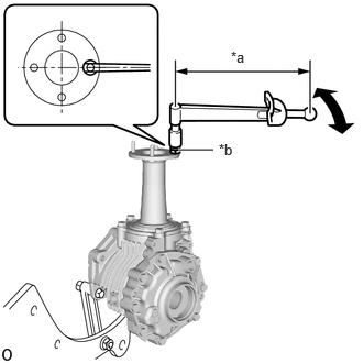
| *a | Torque Wrench Fulcrum Length |
| *b | Double Nut |
Install the double nut to the rear transfer output shaft sub-assembly stud bolt and set the torque wrench into place.
- HINT:
-
Adjust the double nut until the torque wrench is straight.
Using a torque wrench, check the total preload (starting torque) with the teeth of the drive pinion and ring gear in contact.
- Total Preload (Starting Torque):
Item Specified Condition New bearing
(with anti-rust oil)Driven pinion preload + 0.31 to 0.81 N*m (3.17 to 8.25 kgf*cm, 2.75 to 7.16 in.*lbf) Reused bearing
(when coated with gear oil)Driven pinion preload + 0.48 to 0.64 N*m (4.90 to 6.52 kgf*cm, 4.25 to 5.66 in.*lbf)
- NOTICE:
-
Measure the preload after rotating the bearing several times in the forward and backward directions to make sure the bearing is operating correctly.
- HINT:
- ·
0.875,0.135 1.094,0.323 0.219,0.188 10 false L1 1.823,0.125 2.042,0.313 0.219,0.188 10 false L2
When using a torque wrench after changing its effective length, determine the reading of the torque wrench.
Formula T'=T x L2/(L1+L2) T' Reading of torque wrench (N*m (kgf*cm, ft.*lbf)) T Driven pinion preload (N*m (kgf*cm, ft.*lbf)) L1 Distance from center of rear transfer output shaft sub-assembly to center of stud bolt (cm (in.)) L2 Length of torque wrench (cm (in.))
·New bearing (with anti-rust oil):
Distance from center of rear transfer output shaft sub-assembly to center of stud bolt (effective length of 38.9 mm (1.53 in.)) when using a torque wrench (effective length of 160 mm (6.30 in.)): + 0.25 to 0.65 N*m (3 to 6 kgf*cm, 3 to 5 in.*lbf)
·Reused bearing (when coated with gear oil):
Distance from center of rear transfer output shaft sub-assembly to center of stud bolt (effective length of 38.9 mm (1.53 in.)) when using a torque wrench (effective length of 160 mm (6.30 in.)): + 0.39 to 0.51 N*m (4 to 6 kgf*cm, 3.46 to 4.51 in.*lbf)
If the result is not within the specified range, select a No. 2 transfer ring gear mounting case washer (for preload adjustment) from the table below and reinstall it to bring the result within the specified range.
- HINT:
Insufficient Preload Excessive Preload No. 2 transfer ring gear mounting case washer
(for preload adjustment)Increase thickness Decrease thickness
- No. 2 Transfer Ring Gear Mounting Case Washer (for preload adjustment):
Part No. Thickness Identifying Mark Part No. Thickness Identifying Mark 36266-52010 1.18 mm (0.0465 in.) A0 36266-52230 1.62 mm (0.0638 in.) C2 36266-52020 1.20 mm (0.0472 in.) A1 36266-52240 1.64 mm (0.0646 in.) C3 36266-52030 1.22 mm (0.0480 in.) A2 36266-52250 1.66 mm (0.0654 in.) C4 36266-52040 1.24 mm (0.0488 in.) A3 36266-52260 1.68 mm (0.0661 in.) C5 36266-52050 1.26 mm (0.0496 in.) A4 36266-52270 1.70 mm (0.0669 in.) C6 36266-52060 1.28 mm (0.0504 in.) A5 36266-52280 1.72 mm (0.0677 in.) C7 36266-52070 1.30 mm (0.0512 in.) A6 36266-52290 1.74 mm (0.0685 in.) C8 36266-52080 1.32 mm (0.0520 in.) A7 36266-52300 1.76 mm (0.0693 in.) C9 36266-52090 1.34 mm (0.0528 in.) A8 36266-52310 1.78 mm (0.0701 in.) D0 36266-52100 1.36 mm (0.0535 in.) A9 36266-52320 1.80 mm (0.0709 in.) D1 36266-52110 1.38 mm (0.0543 in.) B0 36266-52330 1.82 mm (0.0717 in.) D2 36266-52120 1.40 mm (0.0551 in.) B1 36266-52340 1.84 mm (0.0724 in.) D3 36266-52130 1.42 mm (0.0559 in.) B2 36266-52350 1.86 mm (0.0732 in.) D4 36266-52140 1.44 mm (0.0567 in.) B3 36266-52360 1.88 mm (0.0740 in.) D5 36266-52150 1.46 mm (0.0575 in.) B4 36266-52370 1.90 mm (0.0748 in.) D6 36266-52160 1.48 mm (0.0583 in.) B5 36266-52380 1.92 mm (0.0756 in.) D7 36266-52170 1.50 mm (0.0591 in.) B6 36266-52390 1.94 mm (0.0764 in.) D8 36266-52180 1.52 mm (0.0598 in.) B7 36266-52400 1.96 mm (0.0772 in.) D9 36266-52190 1.54 mm (0.0606 in.) B8 36266-52410 1.98 mm (0.0780 in.) E0 36266-52200 1.56 mm (0.0614 in.) B9 36266-52420 2.00 mm (0.0787 in.) E1 36266-52210 1.58 mm (0.0622 in.) C0 36266-52430 2.02 mm (0.0795 in.) E2 36266-52220 1.60 mm (0.0630 in.) C1 - - -
16.ADJUST TOOTH CONTACT BETWEEN RING GEAR AND DRIVE PINION
Rotate the rear transfer output shaft sub-assembly several times in the forward and backward directions.
Remove the transfer ring gear and check the tooth contact.
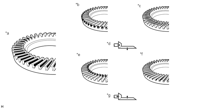
| *a | Proper Contact | *b | Heel Contact |
| *c | Face Contact | *d | Select an adjusting washer that will shift the drive pinion closer to the ring gear (*b, *c) |
| *e | Toe Contact | *f | Flank Contact |
| *g | Select an adjusting washer that will shift the drive pinion away from the ring gear (*e, *f) | - | - |
- NOTICE:
- ·
Check the tooth contact at 4 or more locations on the transfer ring gear.
·When replacing washers (adjusting the backlash, preload or tooth contact pattern), reapply a coat of Prussian Blue.
- HINT:
-
The Prussian Blue pattern indicates the tooth contact points.
In instances of face contact or flank contact, perform the following procedure.
Move and adjust the transfer ring gear using the No. 2 transfer ring gear mounting case washer (for preload adjustment) and the No. 1 ring gear mounting case washer (for backlash adjustment).
In instances of heel contact or toe contact, perform the following procedure.
Select a transfer output shaft washer (for tooth contact adjustment) from the table below, and move and adjust the transfer driven pinion.
- Transfer Output Shaft Washer (for tooth contact adjustment):
Part No. Thickness Identifying Mark Part No. Thickness Identifying Mark 36275-52010 1.02 mm (0.0402 in.) 01 36275-52150 1.30 mm (0.0512 in.) 15 36275-52020 1.04 mm (0.0409 in.) 02 36275-52160 1.32 mm (0.0520 in.) 16 36275-52030 1.06 mm (0.0417 in.) 03 36275-52170 1.34 mm (0.0528 in.) 17 36275-52040 1.08 mm (0.0425 in.) 04 36275-52180 1.36 mm (0.0535 in.) 18 36275-52050 1.10 mm (0.0433 in.) 05 36275-52190 1.38 mm (0.0543 in.) 19 36275-52060 1.12 mm (0.0441 in.) 06 36275-52200 1.40 mm (0.0551 in.) 20 36275-52070 1.14 mm (0.0449 in.) 07 36275-52210 1.42 mm (0.0559 in.) 21 36275-52080 1.16 mm (0.0457 in.) 08 36275-52220 1.44 mm (0.0567 in.) 22 36275-52090 1.18 mm (0.0465 in.) 09 36275-52230 1.46 mm (0.0575 in.) 23 36275-52100 1.20 mm (0.0472 in.) 10 36275-52240 1.48 mm (0.0583 in.) 24 36275-52110 1.22 mm (0.0480 in.) 11 36275-52250 1.50 mm (0.0591 in.) 25 36275-52120 1.24 mm (0.0488 in.) 12 36275-52260 1.52 mm (0.0598 in.) 26 36275-52130 1.26 mm (0.0496 in.) 13 36275-52270 1.54 mm (0.0606 in.) 27 36275-52140 1.28 mm (0.0504 in.) 14 36275-52280 1.56 mm (0.0614 in.) 28
If the tooth contact has been adjusted, recheck the backlash, preload and tooth contact pattern.
36121
17.REMOVE NO. 1 TRANSFER CASE COVER
Remove the 8 bolts and No. 1 transfer case cover from the transfer case.
18.REMOVE TRANSFER RING GEAR
Remove the transfer ring gear from the transfer case.
36202
19.REMOVE REAR TRANSFER OUTPUT SHAFT SUB-ASSEMBLY
Remove the 5 bolts and rear transfer output shaft sub-assembly from the transfer case.
36111G
20.INSTALL TRANSFER CASE STRAIGHT PIN
Using a plastic-faced hammer, install the 4 transfer case straight pins to the locations shown in the illustration.
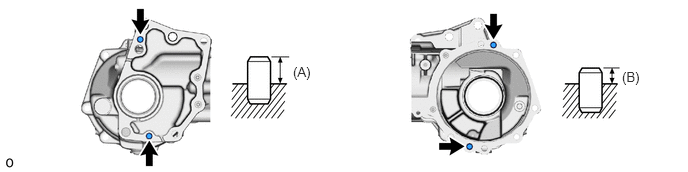
- Drive in Depth (A):
10.8 to 11.8 mm (0.426 to 0.464 in.)
- Drive in Depth (B):
6.5 to 7.5 mm (0.256 to 0.295 in.)
36202
21.INSTALL REAR TRANSFER OUTPUT SHAFT SUB-ASSEMBLY
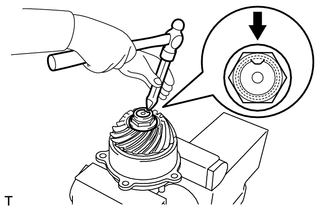
Secure the rear transfer output shaft sub-assembly in a vise between aluminum plates.
- NOTICE:
-
Do not overtighten the vise.
Using a chisel and hammer, stake the transfer gear nut.
- NOTICE:
-
Fully stake the transfer gear nut along the entire groove.
Install the rear transfer output shaft sub-assembly to the transfer case with the 5 bolts.
- Torque:
- 38 N*m (387 kgf*cm, 28 ft.*lbf)
- NOTICE:
-
Do not scratch, twist or break the O-ring.
22.INSTALL TRANSFER RING GEAR
Install the transfer ring gear to the transfer case.
36121
23.INSTALL NO. 1 TRANSFER CASE COVER
Clean and degrease the installation surfaces of the transfer case and No. 1 transfer case cover.
- NOTICE:
-
Do not damage the installation surface.
Apply seal packing 1281 to the transfer case in a continuous bead at the position shown in the illustration.
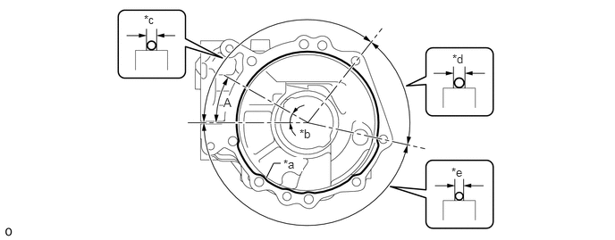
| *a | Seal Packing | *b | 30° |
| *c | Seal Width 2.5 to 3.5 mm (0.099 to 0.137 in.) | *d | Seal Width 3.0 to 4.0 mm (0.119 to 0.157 in.) |
| *e | Seal Width 2.0 to 3.0 mm (0.079 to 0.118 in.) | - | - |
- Seal Packing:
Toyota Genuine Seal Packing 1281, Three Bond 1281 or equivalent
- NOTICE:
- ·
After applying seal packing, install the part within 3 minutes and tighten it within 10 minutes.
·Overlap the seal packing application start and end positions by 10 mm or more.
·Place the seal packing application start position within the range (A).
·Apply seal packing in a continuous line.
Install the No. 1 transfer case cover with the 8 bolts.
- Torque:
- 47 N*m (479 kgf*cm, 35 ft.*lbf)
36111B
24.INSTALL TRANSFER CASE OIL SEAL
36113D
25.INSTALL TRANSFER CASE OIL SEAL RH
Coat the lip of a new transfer case oil seal RH with MP grease.
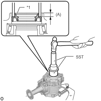
| *1 | Transfer Case Oil Seal RH |
Using SST and a hammer, tap in the transfer case oil seal RH as shown in the illustration.
- SST
- 09631-32020
09223-46011
- Drive in Depth (A):
7.5 to 8.5 mm (0.296 to 0.334 in.)
- NOTICE:
- ·
Tap the transfer case oil seal RH uniformly so that the transfer case oil seal RH is straight.
·Do not tap the transfer case oil seal RH in too far.
36111H
26.INSTALL TRANSFER CASE BREATHER PLUG
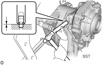
Using SST and a hammer, tap in a new transfer case breather plug until it meets the transfer case.
- SST
- 09612-10093 (09612-10061)
36114L
27.INSTALL TRANSFER FILLER PLUG
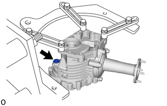
Using a 10 mm hexagon socket wrench, install a new gasket and the transfer filler plug.
- Torque:
- 39 N*m (398 kgf*cm, 29 ft.*lbf)
36114F
28.INSTALL TRANSFER DRAIN PLUG
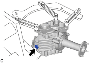
Using a 10 mm hexagon socket wrench, install a new gasket and the transfer drain plug.
- Torque:
- 39 N*m (398 kgf*cm, 29 ft.*lbf)
36114B
29.INSTALL NO. 1 TRANSFER CASE PLUG
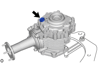
Install a new gasket and the No. 1 transfer case plug.
- Torque:
- 49 N*m (500 kgf*cm, 36 ft.*lbf)
36100
30.REMOVE TRANSFER ASSEMBLY
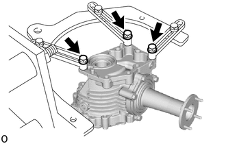
Remove the transfer assembly from the overhaul attachment.
36100A
31.INSTALL TRANSFER AND TRANSAXLE SETTING STUD BOLT
Clean the transfer and transaxle setting stud bolt holes.
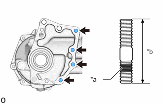
| *a | Adhesive 1324 |
| *b | 64 mm (2.52 in.) |
Using 2 nuts, install 4 new stud bolts in the locations shown in the illustration.
- Torque:
- 39.2 N*m (400 kgf*cm, 29 ft.*lbf)
- NOTICE:
-
Install the shorter threaded part of each stud bolt to the transfer side.