GF1A TRANSFER / 4WD / AWD TRANSFER ASSEMBLY DISASSEMBLY
CAUTION / NOTICE / HINT
- NOTICE:
-
Before installation of each part, thoroughly clean and dry it. Then apply grease or oil as necessary. Do not use alkaline chemicals to clean aluminum parts, rubber parts or precoated bolts. Also, do not use non-residue solvent or other cleaning oils to clean O-rings, oil seals or rubber parts.
PROCEDURE

 36100A
1.REMOVE TRANSFER AND TRANSAXLE SETTING STUD BOLT
36100A
1.REMOVE TRANSFER AND TRANSAXLE SETTING STUD BOLT
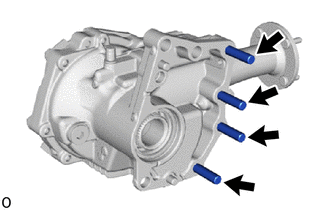
Using 2 nuts, remove the 4 transfer and transaxle setting stud bolts.
36100
2.SECURE TRANSFER ASSEMBLY
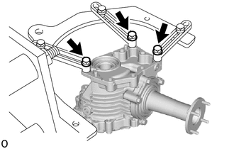
Secure the transfer assembly to the overhaul attachment.
36111G
3.REMOVE TRANSFER CASE STRAIGHT PIN
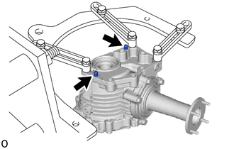
Remove the 2 transfer case straight pins.
36114B
4.REMOVE NO. 1 TRANSFER CASE PLUG
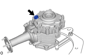
Remove the No. 1 transfer case plug and gasket.
36114F
5.REMOVE TRANSFER DRAIN PLUG
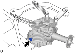
Using a 10 mm hexagon socket wrench, remove the transfer drain plug and gasket.
36114L
6.REMOVE TRANSFER FILLER PLUG
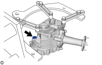
Using a 10 mm hexagon socket wrench, remove the transfer filler plug and gasket.
36111H
7.REMOVE TRANSFER CASE BREATHER PLUG
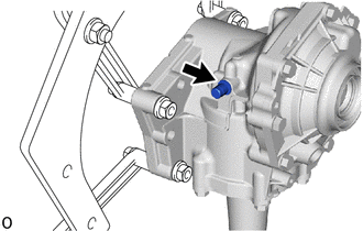
Using a chisel and hammer, slightly pry out the transfer case breather plug.
Using a screwdriver, lightly pry up and remove the transfer case breather plug.
36111B
8.REMOVE TRANSFER CASE OIL SEAL
36113D
9.REMOVE TRANSFER CASE OIL SEAL RH
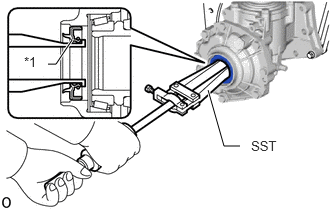
| *1 | Transfer Case Oil Seal RH |
Using SST, remove the transfer case oil seal RH from the No. 1 transfer case cover.
- SST
- 09308-00010
- NOTICE:
-
Do not scratch the press-fitting surface of the transfer case oil seal RH.
10.INSPECT TOTAL PRELOAD
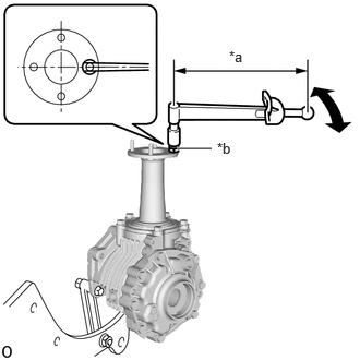
| *a | Torque Wrench Fulcrum Length |
| *b | Double Nut |
Install the double nut to the rear transfer output shaft sub-assembly stud bolt and set the torque wrench into place.
- HINT:
-
Adjust the double nut until the torque wrench is straight.
Using a torque wrench, check the total preload (starting torque) with the teeth of the drive pinion and ring gear in contact.
- Torque:
- Total preload (starting torque) : 0.87 to 2.85 N*m (8.88 to 29.06 kgf*cm, 7.71 to 25.22 in.*lbf)
- HINT:
- ·
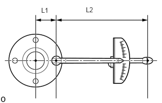 0.875,0.135 1.094,0.323 0.219,0.188 10 false L1 1.823,0.125 2.042,0.313 0.219,0.188 10 false L2
When using a torque wrench after changing its effective length, determine the reading of the torque wrench.
Formula T'=T x L2/(L1+L2) T' Reading of torque wrench (N*m (kgf*cm, ft.*lbf)) T Driven pinion preload (N*m (kgf*cm, ft.*lbf)) L1 Distance from center of rear transfer output shaft sub-assembly to center of stud bolt (cm (in.)) L2 Length of torque wrench (cm (in.))
·Distance from center of rear transfer output shaft sub-assembly to center of stud bolt (effective length of 38.9 mm (1.53 in.)) when using a torque wrench (effective length of 160 mm (6.30 in.)): 0.70 to 2.29 N*m (8 to 23 kgf*cm, 7 to 20 in.*lbf)
11.INSPECT RING GEAR BACKLASH
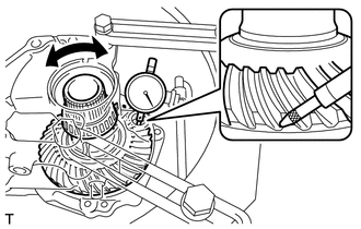
Insert a dial indicator through the transfer filler plug hole, and set it perpendicular to the edge of a ring gear tooth.
If the backlash is not within the specified range, adjust the backlash or repair as necessary.
While securing the rear transfer output shaft sub-assembly by hand, rotate the transfer ring gear mounting case forward and backward by hand and measure the backlash of the ring gear and driven pinion.
- Standard Backlash:
0.10 to 0.20 mm (0.00394 to 0.00787 in.)
- NOTICE:
-
Measure the ring gear at 3 or more locations.
36121
12.REMOVE NO. 1 TRANSFER CASE COVER
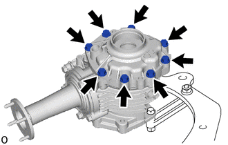
Remove the 8 bolts.
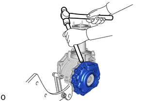
Using a brass bar and hammer, remove the No. 1 transfer case cover from the transfer case.
- NOTICE:
- ·
Put the brass bar against the rib of the No. 1 transfer case cover.
·When removing the No. 1 transfer case cover, be careful not to scratch the installation surface.
- HINT:
-
To prevent the No. 1 transfer case cover from falling, leave 2 of the bolts screwed in by 5 or 6 threads.
13.REMOVE TRANSFER RING GEAR
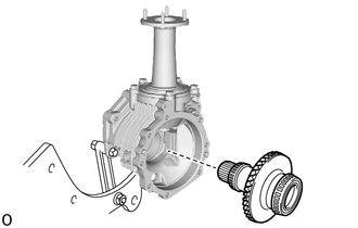
Remove the transfer ring gear from the transfer case.
36111G
14.REMOVE TRANSFER CASE STRAIGHT PIN
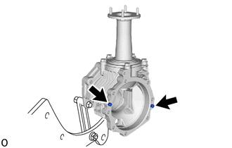
Remove the 2 transfer case straight pins from the transfer case.
15.INSPECT DRIVEN PINION PRELOAD
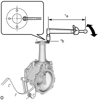
| *a | Torque Wrench Fulcrum Length |
| *b | Double Nut |
Install the double nut to the rear transfer output shaft sub-assembly stud bolt and set the torque wrench into place.
- HINT:
-
Adjust the double nut until the torque wrench is straight.
Using a torque wrench, check the total preload (starting torque) with the teeth of the drive pinion and ring gear in contact.
- Torque:
- Driven pinion preload (starting torque) : 0.39 to 2.21 N*m (3.98 to 22.53 kgf*cm, 3.46 to 19.55 in.*lbf)
- HINT:
- ·
0.875,0.135 1.094,0.323 0.219,0.188 10 false L1 1.823,0.125 2.042,0.313 0.219,0.188 10 false L2
When using a torque wrench after changing its effective length, determine the reading of the torque wrench.
Formula T'=T x L2/(L1+L2) T' Reading of torque wrench (N*m (kgf*cm, ft.*lbf)) T Driven pinion preload (N*m (kgf*cm, ft.*lbf)) L1 Distance from center of rear transfer output shaft sub-assembly to center of stud bolt (cm (in.)) L2 Length of torque wrench (cm (in.))
·Distance from center of rear transfer output shaft sub-assembly to center of stud bolt (effective length of 38.9 mm (1.53 in.)) when using a torque wrench (effective length of 160 mm (6.30 in.)): 0.32 to 1.77 N*m (4 to 18 kgf*cm, 3 to 15 in.*lbf)
36202
16.REMOVE REAR TRANSFER OUTPUT SHAFT SUB-ASSEMBLY
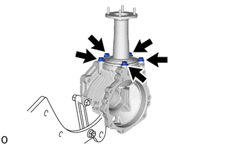
Remove the 5 bolts and rear transfer output shaft sub-assembly from the transfer case.
Mount the rear transfer output shaft sub-assembly in a vise between aluminum plates.
- NOTICE:
-
Do not overtighten the vise.
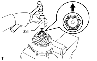
Using SST and a hammer, unstake the transfer gear nut.
- SST
- 09930-00010
- NOTICE:
- ·
Be sure to use SST with the tapered surface facing the shaft.
·Do not grind the tip of SST with a grinder or other device.
·Completely loosen the staked part of the transfer gear nut when removing it.
·Do not damage the threads of the output shaft sub-assembly.
Using a 30 mm socket wrench, remove the transfer gear nut.
17.REMOVE TRANSFER DRIVEN PINION
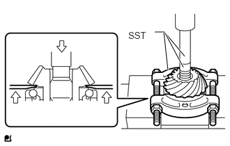
Using SST and a press, remove the transfer driven pinion from the rear transfer output shaft sub-assembly.
- SST
- 09950-00020
09950-60011 (09951-00240)
09950-70010 (09951-07100)
- NOTICE:
-
Support the front transfer driven pinion bearing as shown in the illustration to avoid placing stress on the outer race.
33325A
18.REMOVE REAR TRANSFER OUTPUT SHAFT DUST DEFLECTOR
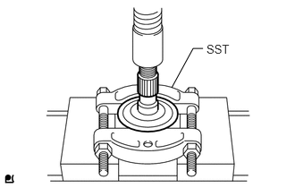
Using SST and a press, remove the rear transfer output shaft dust deflector from the rear transfer output shaft sub-assembly.
- SST
- 09950-00020
41201K
19.REMOVE FRONT TRANSFER DRIVEN PINION BEARING
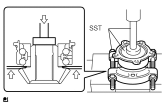
Using SST and a press, remove the front transfer driven pinion bearing from the transfer driven pinion.
- SST
- 09950-00020
09950-60011 (09951-00410)
09950-70010 (09951-07100)
- NOTICE:
-
Support the front transfer driven pinion bearing as shown in the illustration to avoid placing stress on the outer race.
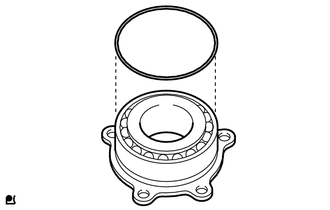
Remove the O-ring from the front transfer driven pinion bearing.
36275E
20.REMOVE TRANSFER OUTPUT SHAFT WASHER
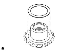
Remove the transfer output shaft washer from the transfer driven pinion.
41301H
21.REMOVE RING GEAR MOUNTING CASE BEARING RH
| *a | Turn |
| *b | Hold |
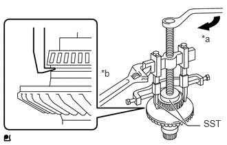
Using SST, remove the ring gear mounting case bearing RH (inner race) from the transfer ring gear mounting case.
- SST
- 09950-40011 (09951-04010, 09952-04010, 09953-04030, 09954-04010, 09955-04061, 09957-04010, 09958-04011)
09950-60011 (09951-00540)
- NOTICE:
- ·
Apply a lubricant to the threads and end of SST.
·Do not deform the cage of the ring gear mounting case bearing RH (inner race) (when reusing the bearing).
·Place identification marks on the left and right ring gear mounting case bearings to distinguish them (backside, teeth side). Then store them separately (when reusing the bearings).
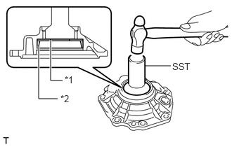
| *1 | No. 2 Transfer Ring Gear Mounting Case Washer |
| *2 | Ring Gear Mounting Case Bearing RH (Outer Race) |
Using SST and a hammer, remove the No. 2 transfer ring gear mounting case washer and ring gear mounting case bearing RH (outer race) from the No. 1 transfer case cover.
- SST
- 09310-35010
41301H
22.REMOVE RING GEAR MOUNTING CASE BEARING LH
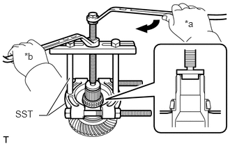
| *a | Turn |
| *b | Hold |
Using SST, remove the ring gear mounting case bearing LH (inner race) from the transfer ring gear mounting case.
- SST
- 09950-00020
09950-00030
- NOTICE:
- ·
Apply a lubricant to the threads and end of SST.
·Do not deform the cage of the ring gear mounting case bearing LH (inner race) (when reusing the bearing).
·Place identification marks on the left and right ring gear mounting case bearings to distinguish them (backside, teeth side). Then store them separately (when reusing the bearings).
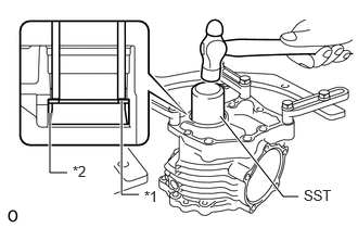
| *1 | No. 1 Ring Gear Mounting Case Washer |
| *2 | Ring Gear Mounting Case Bearing LH (Outer Race) |
Using SST and a hammer, remove the No. 1 ring gear mounting case washer and ring gear mounting case bearing LH (outer race) from the transfer case.
- SST
- 09636-20010
36212L
23.REMOVE SHAFT SNAP RING
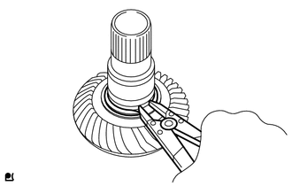
Using a snap ring expander, remove the shaft snap ring.
41319
24.REMOVE TRANSFER RING GEAR MOUNTING CASE
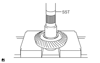
Using SST and a press, remove the transfer ring gear mounting case from the transfer ring gear.
- SST
- 09950-60011 (09951-00400)
36128B
25.REMOVE BREATHER OIL DEFLECTOR
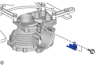
Remove the 2 bolts and breather oil deflector from the transfer case.