MY SETTINGS MY SETTINGS SYSTEM B151487 Facial Recognition Camera Video Line Signal Missing Message
DESCRIPTION
This DTC is stored when LVDS communication between the cabin object recognition camera.
| DTC No. | Detection Item | DTC Detection Condition | Trouble Area |
|---|---|---|---|
| B151487 | Facial Recognition Camera Video Line Signal Missing Message | The following conditions are detected again even after the cabin object recognition camera power supply is turned off then on again:
·
After the cabin object recognition camera power supply is turned off then on again, there is no communication between the cabin object recognition camera and combination meter assembly. ·
When a signal is being sent between the cabin object recognition camera and combination meter assembly, an image malfunction occurs for approximately 2 seconds. |
·
Combination meter assembly ·
Cabin object recognition camera (map light assembly) ·
Wire harness or connector |
WIRING DIAGRAM
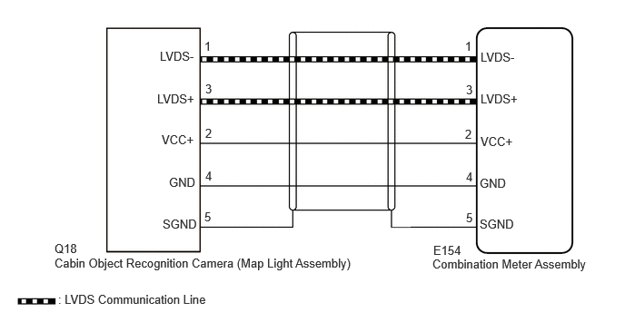
CAUTION / NOTICE / HINT
- NOTICE:
-
When replacing the combination meter assembly, always replace it with a new one. If a combination meter assembly which was installed to another vehicle is used, the information stored in it will not match the information from the vehicle and a DTC may be stored.
PROCEDURE
Disconnect the Q18 cabin object recognition camera (map light assembly) connector.
Measure the voltage according to the value(s) in the table below.
- Standard Voltage:
Tester Connection Condition Specified Condition Click Location & Routing(Q18)Location & Routingewd_type=routing;type=c;code=Q18
Click Connector(Q18)Body>Roof Wire>Cabin Object Recognition Sensorewd_type=component;type=c;code=Q18;pinno=2
Q18-2 (VCC+) - Body ground Drivers door open → close 11 to 14 V Q18-2 (VCC+) - Body ground Drivers door open Below 1 V
Measure the resistance according to the value(s) in the table below.
- Standard Resistance:
Tester Connection Condition Specified Condition Click Location & Routing(Q18)Location & Routingewd_type=routing;type=c;code=Q18
Click Connector(Q18)Body>Roof Wire>Cabin Object Recognition Sensorewd_type=component;type=c;code=Q18;pinno=4,5
Q18-4 (GND) - Body ground Always Below 1 Ω Q18-5 (SGND) - Body ground Always Below 1 Ω
- Result:
Proceed to OK NG
OK
NG
Disconnect the E154 combination meter assembly connector.
Measure the resistance according to the value(s) in the table below.
- Standard Resistance:
Tester Connection Condition Specified Condition Click Location & Routing(Q18,E154)Location & Routingewd_type=routing;type=c,c;code=Q18,E154
Click Connector(Q18)Body>Roof Wire>Cabin Object Recognition Sensorewd_type=component;type=c;code=Q18;pinno=1,3,2,4,5
Click Connector(E154)Instrument Panel>Instrument Panel Wire / Radio Wiring Sub-Assy / Telephone Computer Wire>Combination Meter Assemblyewd_type=component;type=c;code=E154;pinno=1,3,2,4,5
Q18-1 (LVDS-) - E154-1 (LVDS-) Always Below 1 Ω Q18-1 (LVDS-) or E154-1 (LVDS-) - Body ground Always 10 kΩ or higher Q18-3 (LVDS+) - E154-3 (LVDS+) Always Below 1 Ω Q18-3 (LVDS+) or E154-3 (LVDS+) - Body ground Always 10 kΩ or higher Q18-2 (VCC+) - E154-2 (VCC+) Always Below 1 Ω Q18-2 (VCC+) or E154-2 (VCC+) - Body ground Always 10 kΩ or higher Q18-4 (GND) - E154-4 (GND) Always Below 1 Ω Q18-4 (GND) or E154-4 (GND) - Body ground Always 10 kΩ or higher Q18-5 (SGND) - E154-5 (SGND) Always Below 1 Ω Q18-5 (SGND) or E154-5 (SGND) - Body ground Always 10 kΩ or higher
- Result:
Proceed to OK NG
OK
NG
Replace the cabin object recognition camera (map light assembly) with a new or known good one.
- Result:
Proceed to NEXT
NEXT
Clear the DTCs.
- Body Electrical > Combination Meter > Clear DTCs
- 50002 409
Turn the ignition switch off.
Turn the ignition switch to ON.
Check for DTCs.
- Body Electrical > Combination Meter > Trouble Codes
- 50001 409
- OK:
DTC B151487 is outputs.
- Result:
Proceed to OK NG
OK
NG