PARKING BRAKE FORCED RELEASE OPERATION METHOD
CAUTION / NOTICE / HINT
- CAUTION:
-
-
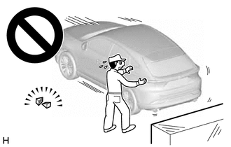
If work is performed without first securing the vehicle, the vehicle may start moving and cause a serious accident or other disaster. Therefore, be sure to use wheel chocks to secure the vehicle before performing work.
PROCEDURE

 1. PRECAUTION
67914B
2.REMOVE FRONT DOOR SCUFF PLATE LH
67913B
3.REMOVE FRONT DOOR SCUFF PLATE RH
- HINT:
-
Use the same procedure as for the LH side.
62112
4.REMOVE COWL SIDE TRIM BOARD LH
62111C
5.REMOVE COWL SIDE TRIM BOARD RH
- HINT:
-
Use the same procedure as for the LH side.
58416K
6.REMOVE REAR NO. 2 FLOOR BOARD (for HV Model)
65351A
7.REMOVE BATTERY HOLE COVER (for HV Model)
8. PARKING BRAKE FORCED RELEASE
- CAUTION:
-
Work on a level surface to ensure safety.
- NOTICE:
- ·
To release the parking brake, follow the procedure for when using SST.
·If the parking brake cannot be released, follow the procedure for when not using SST.
·When moving the vehicle after releasing the parking brake, install all parts and do not connect the 2 connectors shown in the illustration.
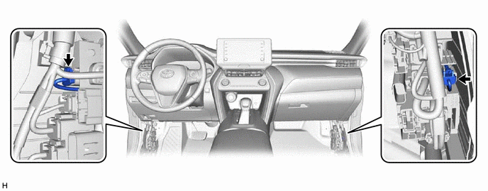
·If the ignition switch is ON or the hybrid system or engine is started with the 2 connectors disconnected, a DTC may be stored. Clear any DTCs after performing work.
for HV Model: Click hereBrake>PARKING BRAKE>ELECTRIC PARKING BRAKE SYSTEM (for HV Model)>DTC CHECK / CLEAR202111,999999,_54,_111818,_0501133,RM100000001Z519,
for Gasoline Model: Click hereBrake>PARKING BRAKE>ELECTRIC PARKING BRAKE SYSTEM (for Gasoline Model)>DTC CHECK / CLEAR202111,999999,_54,_111818,_0501134,RM100000001Z528,
When using SST:
Park the vehicle on a level surface and move the shift lever to P.
Turn the ignition switch off and use wheel chocks to secure the vehicle.
Disconnect the 2 connectors shown in the illustration.
Connect SST (09756-48020) to SST (09756-48070).
- SST
- 09756-48020 09756-48070
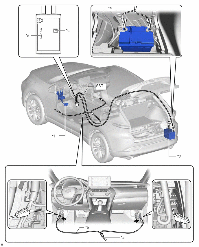
| *1 | Brake Pedal | *2 | Auxiliary Battery |
| *a | SST (09756-48020) | *b | SST (09756-48070) |
| *c | Release Button | *d | Finished Light |

|
Connector | - | - |
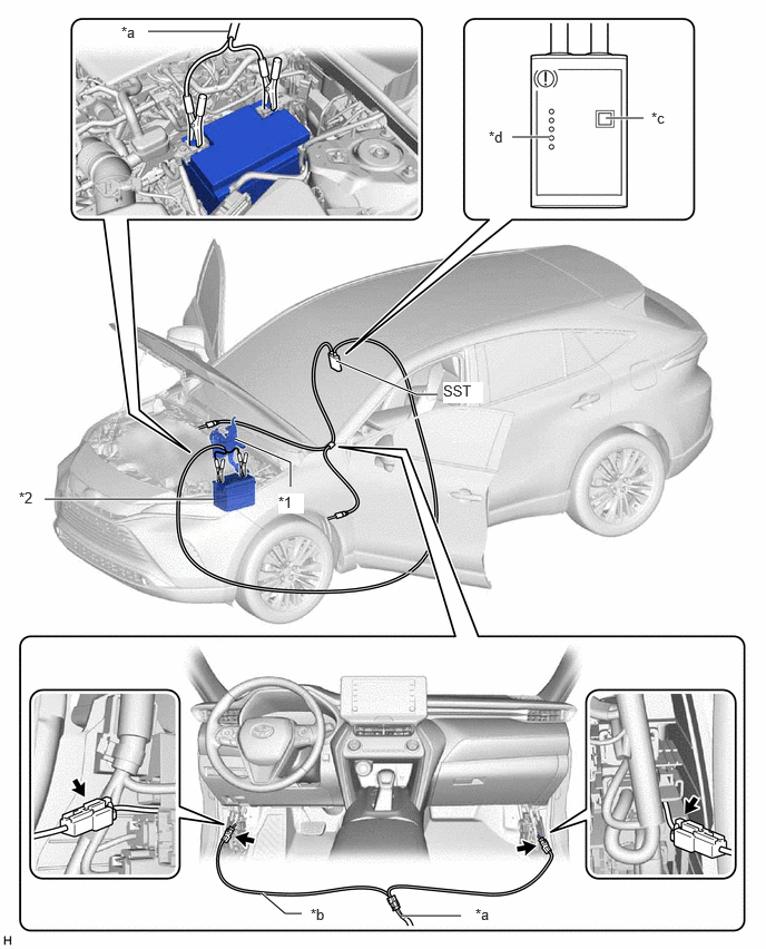
| *1 | Brake Pedal | *2 | Battery |
| *a | SST (09756-48020) | *b | SST (09756-48070) |
| *c | Release Button | *d | Finished Light |
|
|
Connector | - | - |
Connect SST (09756-48070) to the 2 connectors.
Connect SST (09756-48020) to the auxiliary battery.
Push the release button on SST (09756-48020) with the brake pedal depressed.
- CAUTION:
-
The vehicle may suddenly move when the parking brake is released. Make sure to perform the release operation with the brake pedal depressed.
- HINT:
- ·
Confirm that the parking brake is operating by listening for operation sounds.
·If no operation sounds are heard, push the release button on SST (09756-48020) with the brake pedal depressed.
·The parking brake may not release if the auxiliary battery voltage is too low. In this case, perform the release operation again using a fully charged or new auxiliary battery.
When the finished light of SST (09756-48020) illuminates, release the brake pedal.
Move the vehicle forward and rearward to check that the parking brake is released.
- CAUTION:
-
Be careful when performing this operation. The vehicle may suddenly move.
- NOTICE:
-
When moving the vehicle after releasing the parking brake, check that the 2 connectors are disconnected.
When not using SST:
- NOTICE:
-
Perform the following procedure only when the parking brake cannot be released using SST.
- HINT:
- ·
Use the same procedure for the RH side and LH side.
·The following procedure is for the LH side.
Park the vehicle on a level surface and check that the shift lever is in P.
Turn the ignition switch off and use wheel chocks to secure the vehicle.
Check that the 2 connectors shown in the illustration have been disconnected.
Remove the rear wheel.
- CAUTION:
-
When using a jack to lift the vehicle, make sure to support the vehicle using safety stands. Do not work on the vehicle with it supported only by a jack.
Disconnect the No. 2 parking brake wire assembly connector from the parking brake actuator assembly.
Remove the parking brake actuator assembly from the rear disc brake cylinder assembly.
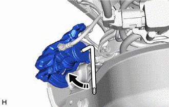
Insert an L-shaped T45 "TORX" wrench into the rear disc brake cylinder assembly.
Turn the L-shaped T45 "TORX" wrench 2 full rotations clockwise to release the parking brake lock.
- NOTICE:
-
When moving the vehicle after releasing the parking brake, install all parts and do not connect the 2 connectors shown in the illustration.
-
65351A
9.INSTALL BATTERY HOLE COVER (for HV Model)
58416K
10.INSTALL REAR NO. 2 FLOOR BOARD (for HV Model)
62112
11.INSTALL COWL SIDE TRIM BOARD LH
62111C
12.INSTALL COWL SIDE TRIM BOARD RH
67914B
13.INSTALL FRONT DOOR SCUFF PLATE LH
67913B
14.INSTALL FRONT DOOR SCUFF PLATE RH