RM38N0EC
_55
Steering
_111820
STEERING COLUMN
_0504451
HEATED STEERING WHEEL SYSTEM
G
STEERING COLUMN HEATED STEERING WHEEL SYSTEM INSPECTION
PROCEDURE

 84255
1.INSPECT STEERING HEATER SWITCH
84255
1.INSPECT STEERING HEATER SWITCH
a.
1.563,1.896 1.604,1.438
false
1.26,1.865 1.396,1.438
false
2.083,1.885 1.99,1.438
false
1.167,1.906 1.479,2.104
0.313,0.198
10
false
IG
2.083,1.927 2.396,2.125
0.313,0.198
10
false
B
0.104,0.094 0.417,0.25
0.313,0.156
10
false
*a
1.521,1.938 1.833,2.135
0.313,0.198
10
false
E
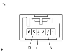
| *a | Component without harness connected
(Steering Heater Switch) |
Confirm that no switches are stuck on or off.
b.
Measure the resistance according to the value(s) in the table below.
- Standard Resistance:
Tester Connection Condition Specified Condition Click Location & Routing(E39)Location & Routingewd_type=routing;type=c;code=E39
Click Connector(E39)Instrument Panel>Instrument Panel Wire / Radio Wiring Sub-Assy / Telephone Computer Wire>Steering Heater Switchewd_type=component;type=c;code=E39;pinno=5,2
E39-5 (IG) - E39-2 (B) Steering heater switch is pushed Below 1 Ω E39-5 (IG) - E39-2 (B) Steering heater switch is not pushed 10 kΩ or higher
c.
Indicator Inspection
i.
Apply battery voltage to the steering heater switch and check that the indicator illuminates.
- OK:
Condition Specified Condition Battery positive (+) → Terminal 5 (IG)
Battery negative (-) → Terminal 4 (E)Illuminates