M20C-FKS, M20D-FKS EMISSION CONTROL EGR COOLER INSTALLATION
CAUTION / NOTICE / HINT
- NOTICE:
-
This procedure includes the installation of small-head bolts. Refer to Small-Head Bolts of Basic Repair Hint to identify the small-head bolts.
PROCEDURE

 25680
1.INSTALL EGR COOLER ASSEMBLY
25680
1.INSTALL EGR COOLER ASSEMBLY
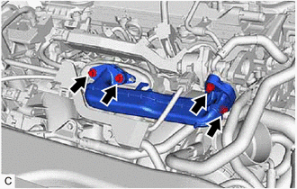
Using an 8 mm socket wrench, loosen the 4 bolts of the No. 1 EGR pipe sub-assembly.
- HINT:
- ·
As the bolts of the No. 1 EGR pipe sub-assembly are only to be loosened, it is not necessary to replace the EGR inlet gasket and EGR valve adapter gasket.
·If the No. 1 EGR pipe sub-assembly is removed, it is necessary to replace the EGR inlet gasket and EGR valve adapter gasket with new ones.
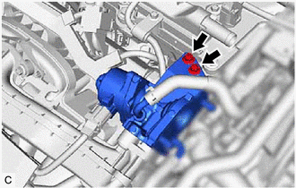
Using an 8 mm socket wrench, loosen the 2 bolts of the EGR valve assembly.
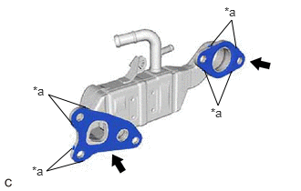
| *a | Claw |
Install a new EGR cooler gasket to the EGR cooler assembly.
- NOTICE:
-
Make sure that the claws of the EGR cooler gasket are toward the EGR cooler assembly side.
Install a new EGR valve gasket to the EGR cooler assembly.
- NOTICE:
-
Make sure that the claws of the EGR valve gasket are toward the EGR cooler assembly side.
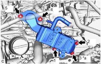
| *a | Bolt or Nut |
Type A:
Temporarily install the EGR cooler assembly to the cylinder head sub-assembly and EGR valve assembly with the 3 bolts and 2 nuts.
Tighten the 3 bolts and 2 nuts in the order shown in the illustration.
- Torque:
- 24 N*m (245 kgf*cm, 18 ft.*lbf)
Type B:
Temporarily install the EGR cooler assembly to the cylinder head sub-assembly and EGR valve assembly with the 2 bolts and 3 nuts.
Tighten the 2 bolts and 3 nuts in the order shown in the illustration.
- Torque:
- 24 N*m (245 kgf*cm, 18 ft.*lbf)
Using an 8 mm socket wrench, install the wire harness clamp bracket to the EGR cooler assembly with the 2 bolts.
- Torque:
- 10 N*m (102 kgf*cm, 7 ft.*lbf)
Connect the No. 3 water by-pass hose and No. 4 water by-pass hose to the EGR cooler assembly and slide the 2 clips to secure them.
Using an 8 mm socket wrench, tighten the 2 bolts of the EGR valve assembly.
- Torque:
- 10 N*m (102 kgf*cm, 7 ft.*lbf)
Using an 8 mm socket wrench, tighten the 4 bolts of the No. 1 EGR pipe sub-assembly.
- Torque:
- 10 N*m (102 kgf*cm, 7 ft.*lbf)
82121
2.CONNECT ENGINE WIRE
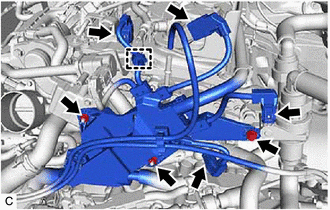
Engage the wire harness clamp and connect the engine wire.
Connect the 4 connectors.
Install the bolt and 2 nuts.
- Torque:
- 10 N*m (102 kgf*cm, 7 ft.*lbf)

Engage the wire harness clamp.
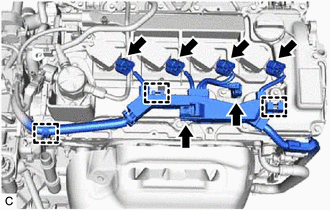
Engage the 3 wire harness clamps.
Connect the 6 connectors.
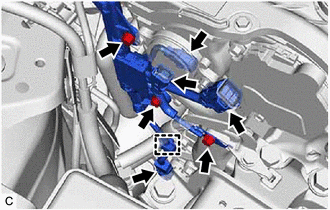
Engage the wire harness clamp.
Connect the 4 connectors.
Install the 3 bolts.
- Torque:
- 10 N*m (102 kgf*cm, 7 ft.*lbf)
3.INSTALL BATTERY
4.INSTALL AIR CLEANER ASSEMBLY WITH AIR CLEANER HOSE
17751
5.INSTALL INLET AIR CLEANER ASSEMBLY
12601B
6.INSTALL NO. 1 ENGINE COVER SUB-ASSEMBLY
7.ADD ENGINE COOLANT
8.INSPECT FOR COOLANT LEAK