DRIVE SHAFT / PROPELLER SHAFT REAR DRIVE SHAFT ASSEMBLY(for SFTM Made) REASSEMBLY
PROCEDURE

 1.INSTALL REAR DRIVE SHAFT OUTBOARD JOINT BOOT
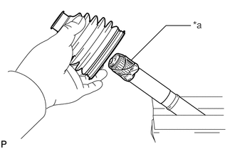
| *a | Protective Tape |
Wrap the splines of the rear drive shaft outboard joint shaft assembly with protective tape to prevent the boot from being damaged.
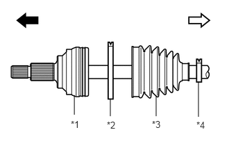
| *1 | Rear Drive Shaft Outboard Joint Assembly |
| *2 | Rear No. 2 Drive Shaft Outboard Joint Boot Clamp |
| *3 | Rear Drive Shaft Outboard Joint Boot |
| *4 | Rear Drive Shaft Outboard Joint Boot Clamp |

|
Outboard joint side |

|
Inboard joint side |
Install new parts to the rear drive shaft outboard joint shaft assembly in the following order:
Rear No. 2 drive shaft outboard joint boot clamp
Rear drive shaft outboard joint boot
Rear drive shaft outboard joint boot clamp
Pack the joint portion of the rear drive shaft outboard joint shaft assembly and rear drive shaft outboard joint boot with grease.
- Standard Grease Capacity:
45 to 65 g (1.59 to 2.29 oz)
Install the rear drive shaft outboard joint boot to the rear drive shaft outboard joint shaft assembly groove.
- NOTICE:
- ·
Do not allow grease to adhere to the boot clamp track of the outboard joint boot.
·Keep the inside of the outboard joint boot free of foreign matter.
42346F
2.INSTALL REAR NO. 2 DRIVE SHAFT OUTBOARD JOINT BOOT CLAMP
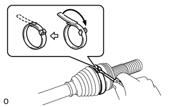
Using a screwdriver, install the rear No. 2 drive shaft outboard joint boot clamp as shown in the illustration.
- NOTICE:
-
Be careful not to damage the rear drive shaft outboard joint boot.
42346D
3.INSTALL REAR DRIVE SHAFT OUTBOARD JOINT BOOT CLAMP
Hold the drive shaft in a vise between aluminum plates.
- NOTICE:
-
Do not overtighten the vise.
Install the rear drive shaft outboard joint boot clamp to the rear drive shaft outboard joint boot.
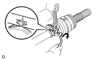
Place SST to the rear drive shaft outboard joint boot clamp, press it against the boot and slightly tighten SST.
- SST
- 09521-24010
Tighten SST so that the rear drive shaft outboard joint boot clamp is pinched.
- NOTICE:
-
Do not overtighten SST.
Remove SST.
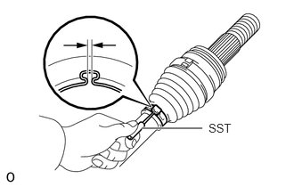
Using SST, measure the clearance of the rear drive shaft outboard joint boot clamp.
- SST
- 09240-00020
- Clearance:
1.2 to 4.0 mm (0.0473 to 0.157 in.)
If the clearance is outside the specified range, retighten SST.
42360D
4.INSTALL REAR DRIVE SHAFT INBOARD JOINT ASSEMBLY
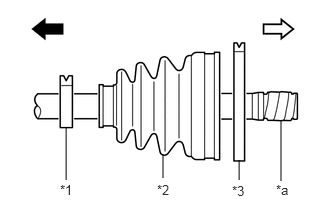
| *1 | Rear Drive Shaft Inboard Joint Boot Clamp |
| *2 | Rear Drive Shaft Inboard Joint Boot |
| *3 | Rear No. 2 Drive Shaft Inboard Joint Boot Clamp |
| *a | Protective Tape |
|
|
Outboard joint side |
|
|
Inboard joint side |
Install new parts to the rear drive shaft outboard joint shaft assembly in the following order:
Rear drive shaft inboard joint boot clamp
Rear drive shaft inboard joint boot
Rear No. 2 drive shaft inboard joint boot clamp
Hold the drive shaft in a vise between aluminum plates.
- NOTICE:
-
Do not overtighten the vise.
Remove the protective tape.
Install the ball cage to the rear drive shaft outboard joint shaft assembly.
- NOTICE:
-
Face the smaller inside diameter side to the rear drive shaft outboard joint shaft assembly and insert.
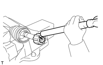
| *a | Matchmark |
Align the matchmarks placed before removal.
Using a brass bar and a hammer, install the inner race to the rear drive shaft outboard joint shaft assembly.
- NOTICE:
-
Be careful not to damage the inner race.
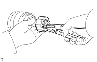
Using a snap ring expander, install a new shaft snap ring to the rear drive shaft outboard joint shaft assembly.

| *a | Matchmark |
Align the matchmarks and install the ball cage to the inner race.
Install the 8 balls with grease to the inner race.
- NOTICE:
-
Be careful not to drop the balls.
- HINT:
-
Apply grease to the balls to keep them from falling.
Pack the rear drive shaft inboard joint assembly and rear drive shaft inboard joint boot with grease.
- Standard Grease Capacity:
85 to 105 g (3.00 to 3.70 oz)
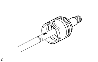
| *a | Matchmark |
Align the matchmarks and install the rear drive shaft inboard joint assembly to the rear drive shaft outboard joint shaft assembly.
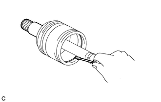
Using a screwdriver, install a new drive shaft snap ring to the rear drive shaft inboard joint assembly.
5.INSTALL REAR DRIVE SHAFT INBOARD JOINT BOOT
Install the rear drive shaft inboard joint boot to the rear drive shaft inboard joint assembly.
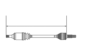
Check whether the drive shaft dimension (A) is within specification.
- Dimension (A):
for LH Side 718.4 mm (2.36 ft.) for RH Side 791.4 mm (2.60 ft.)
42347E
6.INSTALL REAR NO. 2 DRIVE SHAFT INBOARD JOINT BOOT CLAMP
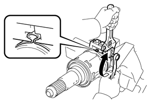
| *a | Turn |
| *b | Hold |
Install the rear No. 2 drive shaft inboard joint boot clamp to the inboard joint boot.
Place SST onto the rear No. 2 drive shaft inboard joint boot clamp, press it against the boot and slightly tighten SST.
- SST
- 09521-24010
Tighten SST so that the rear No. 2 drive shaft inboard joint boot clamp is pinched.
- NOTICE:
-
Do not overtighten SST.
Remove SST.
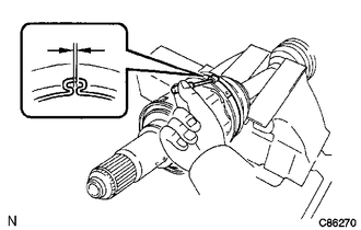
Using SST, measure the clearance of the rear No. 2 drive shaft inboard joint boot clamp.
- SST
- 09240-00021
- Clearance:
1.2 to 4.0 mm (0.0473 to 0.157 in.)
If the clearance is not as specified, retighten SST.
42347D
7.INSTALL REAR DRIVE SHAFT INBOARD JOINT BOOT CLAMP
- HINT:
-
Perform the same procedure as for the rear drive shaft outboard joint boot clamp.
42340B
8.INSPECT REAR DRIVE SHAFT ASSEMBLY