BRAKE CONTROL / DYNAMIC CONTROL SYSTEMS ELECTRONICALLY CONTROLLED BRAKE SYSTEM(for Gasoline Model) ON-VEHICLE INSPECTION
PROCEDURE

 1. WARNING LIGHT AND INDICATOR LIGHT INITIAL CHECK
When the ignition switch is turned to ON, check that the ABS warning light, brake system warning light (red indicator), slip indicator light, VSC OFF indicator light, brake hold standby indicator light and brake hold operated indicator light come on for approximately 3 seconds.
- HINT:
-
If the warning lights and indicator lights does not illuminate or illuminates for more than approximately 3 seconds, perform troubleshooting for the electronically controlled brake system.
47220D
2.INSPECT BRAKE MASTER CYLINDER RESERVOIR ASSEMBLY
Pre-procedure1
Remove the brake master cylinder reservoir filler cap assembly.
Disconnect the brake fluid level warning switch (brake master cylinder reservoir assembly) connector.
Procedure1
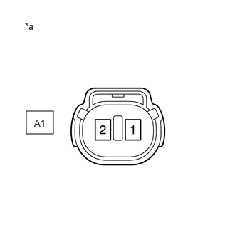
| *a | Component without harness connected
(Brake Fluid Level Warning Switch (Brake Master Cylinder Reservoir Assembly)) |
Measure the resistance according to the value(s) in the table below.
- HINT:
-
A float is located inside the reservoir. Its position changes according to the brake fluid level.
- Standard Resistance:
Tester Connection Condition Specified Condition Click Location & Routing(A1)Location & Routingewd_type=routing;type=c;code=A1
Click Connector(A1)Engine Compartment>Engine Room Main Wire / Transmission Wire>Brake Master Cylinder Sub-Assemblyewd_type=component;type=c;code=A1;pinno=1,2
A1-1 - A1-2 Switch off (float up) 10 kΩ or higher A1-1 - A1-2 Switch on (float down) Below 1 Ω
Post-procedure1
If there is no problem after finishing the above check, adjust the brake fluid level to the MAX level.
47110
3.INSPECT BRAKE PEDAL SUPPORT ASSEMBLY
Pre-procedure1
Disconnect the brake pedal load sensing switch (brake pedal support assembly) connector.
Procedure1
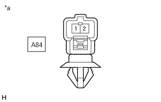
| *a | Component without harness connected
(Brake Pedal Load Sensing Switch (Brake Pedal Support Assembly)) |
Measure the resistance according to the value(s) in the table below.
- Standard Resistance:
Tester Connection Condition Specified Condition Click Location & Routing(A84)Location & Routingewd_type=routing;type=c;code=A84
Click Connector(A84)Instrument Panel>Engine Room Main Wire>Brake Pedal Support Assemblyewd_type=component;type=c;code=A84;pinno=1,2
A84-1 - A84-2 Brake pedal load sensing switch on (Brake pedal released) 203 to 223 Ω A84-1 - A84-2 Brake pedal load sensing switch off (Brake pedal depressed) 950 to 1050 Ω
If the result is not as specified, replace the brake pedal load sensing switch (brake pedal support assembly).
- NOTICE:
-
Do not remove the brake pedal load sensing switch from the brake pedal support assembly.
Post-procedure1
None
44610
4.INSPECT BRAKE BOOSTER ASSEMBLY
Airtightness check
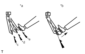
| *a | Correct |
| *b | Incorrect |
| *c | 1st |
| *d | 2nd |
| *e | 3rd |
Start the engine and stop it after 1 or 2 minutes. Slowly depress the brake pedal several times.
- HINT:
-
If the brake pedal can be depressed nearly to the floor the first time, but on the 2nd and 3rd time cannot be depressed as far, the brake booster assembly is airtight.
Depress the brake pedal with the engine running, and stop the engine with the brake pedal depressed.
- HINT:
-
If there is no change in the brake pedal reserve distance while holding the brake pedal depressed for 30 seconds, the brake booster assembly is airtight.
Operation check
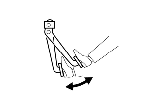
Depress the brake pedal several times with the ignition switch off and check that there is no change in the brake pedal reserve distance when the brake pedal is depressed.
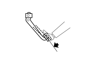
Depress and hold the brake pedal, then start the engine.
- HINT:
-
If the brake pedal goes down slightly, operation is normal.