METER / GAUGE / DISPLAY TRIP SWITCH INSPECTION
PROCEDURE

 84975
1.INSPECT TRIP SWITCH
84975
1.INSPECT TRIP SWITCH
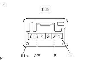
| *a | Component without harness connected
(Trip Switch) |
Measure the resistance according to the value(s) in the table below.
- Standard Resistance:
Tester Connection Condition Specified Condition Click Location & Routing(E33)Location & Routingewd_type=routing;type=c;code=E33
Click Connector(E33)Instrument Panel>Instrument Panel Wire / Radio Wiring Sub-Assy / Telephone Computer Wire>Trip Switchewd_type=component;type=c;code=E33;pinno=5,2
E33-5 (A/B) - E33-2 (E) ODO/TRIP switch pressed Below 50 Ω ODO/TRIP switch not pressed 10 kΩ or higher
If the result is not as specified, replace the trip switch.
Illumination Inspection
Apply auxiliary battery voltage to the trip switch and check that it illuminates.
- OK:
Tester Connection Specified Condition Click Location & Routing(E33)Location & Routingewd_type=routing;type=c;code=E33
Click Connector(E33)Instrument Panel>Instrument Panel Wire / Radio Wiring Sub-Assy / Telephone Computer Wire>Trip Switchewd_type=component;type=c;code=E33;pinno=6,1
E33-6 (ILL+) - Auxiliary battery positive (+)
E33-1 (ILL-) - Auxiliary battery negative (-)Illuminates
If the result is not as specified, replace the trip switch.