REAR SUSPENSION REAR STABILIZER BAR REMOVAL
CAUTION / NOTICE / HINT
The necessary procedures (adjustment, calibration, initialization, or registration) that must be performed after parts are removed and installed, or replaced during rear stabilizer bar removal/installation are shown below.
| Replaced Part or Performed Procedure | Necessary Procedure | Effect/Inoperative Function when Necessary Procedure not Performed | Link |
|---|---|---|---|
| Gas leak from exhaust system is repaired | Inspection After Repair | ·
Poor idle, etc. ·
Engine start function, etc. |
for M20C-FKS, M20D-FKS:
(  202111,202303,_51,_111785,_0504416,RM100000001ZIBM,202303,999999,_51,_111785,_0504416,RM1000000029BFF,) 202111,202303,_51,_111785,_0504416,RM100000001ZIBM,202303,999999,_51,_111785,_0504416,RM1000000029BFF,)
for A25D-FXS, A25F-FXS: ( 202111,202303,_51,_111794,_0505179,RM100000001ZLKE,202303,999999,_51,_111794,_0505179,RM1000000029YT1,)
|
- CAUTION:
-
-
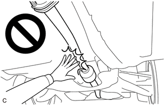
To prevent burns, do not touch the engine, exhaust pipe or other high temperature components while the engine is hot.
PROCEDURE

 1.REMOVE REAR WHEEL
17430
2.REMOVE TAIL EXHAUST PIPE ASSEMBLY
for M20C-FKS, M20D-FKS: Click hereEngine / Hybrid System>M20C-FKS, M20D-FKS (INTAKE / EXHAUST)>EXHAUST PIPE>REMOVAL202111,202303,_51,_111792,_0503719,RM100000001ZFP6,202303,999999,_51,_111792,_0503719,RM1000000029Z2M,
for A25D-FXS, A25F-FXS: Click hereEngine / Hybrid System>A25D-FXS, A25F-FXS (INTAKE / EXHAUST)>EXHAUST PIPE>REMOVAL202111,202303,_51,_111802,_0503724,RM100000001ZFPJ,202303,999999,_51,_111802,_0503724,RM1000000029Z2Z,
58327B
3.REMOVE MAIN MUFFLER HEAT INSULATOR
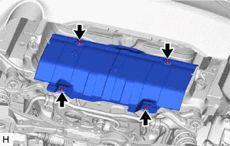
Remove the 4 nuts and main muffler heat insulator from the vehicle.
48840A
4.REMOVE REAR STABILIZER LINK ASSEMBLY LH
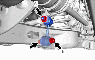
Loosen the nut (A) of the rear stabilizer link assembly LH.
- HINT:
-
If the ball joint turns together with the nut, use a 6 mm hexagon socket wrench to hold the stud bolt.
Loosen the bolt of the rear stabilizer link assembly LH.
- NOTICE:
-
Because the nut (B) has its own stopper, do not turn the nut (B). Loosen the bolt with the nut (B) secured.
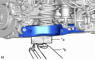
| *a | Wooden Block |
| *b | Jack |
Using a jack and wooden block, support the rear No. 2 suspension arm assembly.
- NOTICE:
- ·
When jacking up the rear No. 2 suspension arm assembly, be sure to jack it up slowly.
·Make sure to perform this operation with the vehicle kept as low as possible.
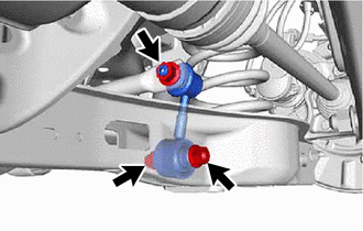
Remove the bolt, 2 nuts and rear stabilizer link assembly LH.
48830D
5.REMOVE REAR STABILIZER LINK ASSEMBLY RH
- HINT:
-
Perform the same procedure as for the LH side.
48812
6.REMOVE REAR STABILIZER BAR
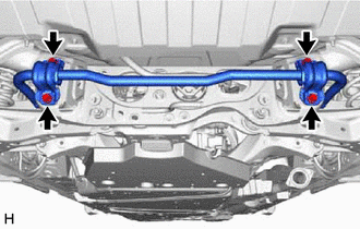
Remove the 4 bolts, rear stabilizer bar, 2 rear No. 1 stabilizer bar brackets, 2 rear lower stabilizer bar brackets and 2 rear stabilizer bushings from the rear suspension member sub-assembly.
48835
7.REMOVE REAR LOWER STABILIZER BRACKET
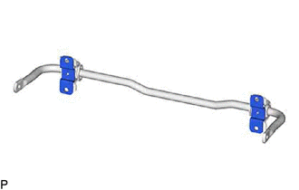
Remove the 2 rear lower stabilizer brackets from the rear stabilizer bushing.
48832A
8.REMOVE REAR NO. 1 STABILIZER BAR BRACKET
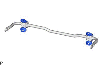
Remove the 2 rear No. 1 stabilizer bar brackets from the rear stabilizer bushing.
48818
9.REMOVE REAR STABILIZER BUSHING
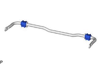
Remove the 2 rear stabilizer bushings from the rear stabilizer bar.