INTERIOR PANELS / TRIM FRONT CONSOLE BOX REASSEMBLY
PROCEDURE

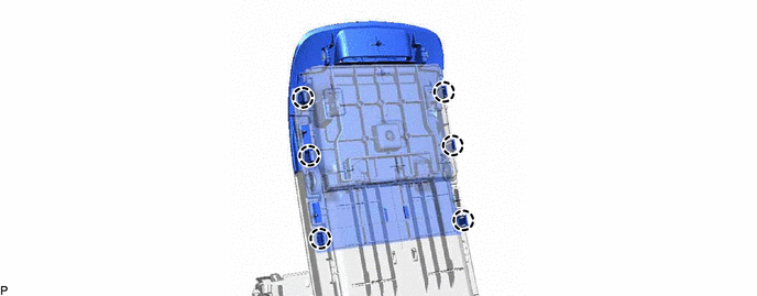
 1.INSTALL CONSOLE COMPARTMENT DOOR LOCK SUB-ASSEMBLY
Engage the 6 claws to install the console compartment door lock sub-assembly.
58905
2.INSTALL CONSOLE COMPARTMENT DOOR SUB-ASSEMBLY
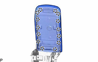
Engage the 14 claws to install the console compartment door sub-assembly.
58863C
3.INSTALL NO. 3 CONSOLE BOX DUCT
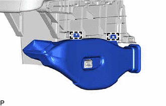
Engage the 2 guides to install the No. 3 console box duct.
58864C
4.INSTALL NO. 4 CONSOLE BOX DUCT
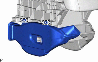
Engage the 2 guides to install the No. 4 console box duct.
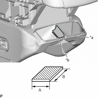
| *a | Nonwoven Tape |
| *b | Line |
Apply new nonwoven tape within the reference line as shown in the illustration.
- HINT:
-
Cut the nonwoven tape to the size shown in the table below.
- Nonwoven Tape Size:
Area Dimension A 40 mm (1.57 in.) B 40 mm (1.57 in.)
58819C
5.INSTALL FRONT CONSOLE BOX FILLER
Clean the No. 1 box side panel surface.
Remove any remaining double-sided tape from the No. 1 box side panel.
Wipe off any tape adhesive residue with cleaner.
Remove the release paper from a new front console box filler.
- HINT:
-
After removing the release paper, keep the exposed adhesive free from foreign matter.
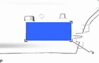
| *a | Line |
Install the front console box filler as shown in the illustration.
- HINT:
- ·
Install the front console box filler along the line on the No. 1 box side panel.
·Press the front console box filler firmly to install it.
58911A
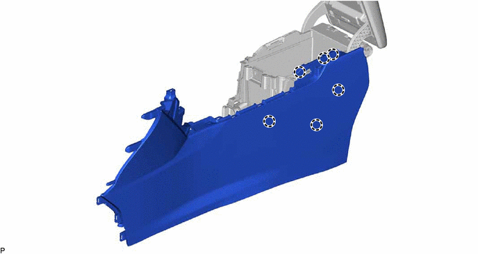
6.INSTALL NO. 1 BOX SIDE PANEL
Engage the 6 claws to install the No. 1 box side panel.
58912C
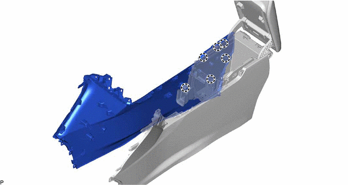
7.INSTALL NO. 2 BOX SIDE PANEL
Engage the 6 claws to install the No. 2 box side panel.
58989A
8.INSTALL CONSOLE BOX RETAINER
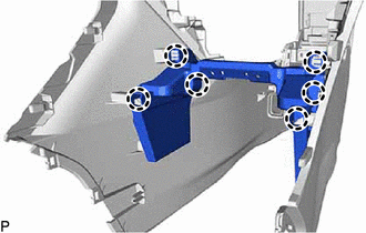
Engage the 6 claws to install the console box retainer.
58862F
9.INSTALL NO. 2 CONSOLE BOX DUCT
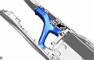
Engage the guide.
Install the No. 2 console box duct with the clip.
85535B
10.INSTALL NO. 1 POWER OUTLET SOCKET COVER
85530
11.INSTALL NO. 1 POWER OUTLET SOCKET ASSEMBLY
58913A
12.INSTALL NO. 3 BOX PANEL
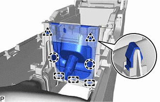
Engage the 3 guides, 2 claws and 2 clips to install the No. 3 box panel.
58805C
13.INSTALL REAR UPPER CONSOLE PANEL SUB-ASSEMBLY
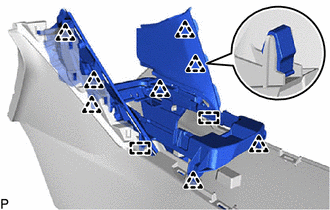
Engage the 2 guides and 8 clips to install the rear upper console panel sub-assembly.
55620
14.INSTALL INSTRUMENT PANEL CUP HOLDER ASSEMBLY
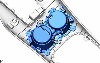
Engage the 2 guides.
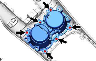
Install the instrument panel cup holder assembly with the 6 screws.
58827A
15.INSTALL CONSOLE BOX POCKET GARNISH
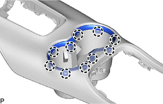
Engage the 10 claws to install the console box pocket garnish.
58862C
16.INSTALL NO. 2 CONSOLE BOX SUPPORT
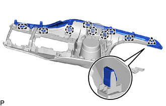
Engage the 5 guides, 3 claws and clip.
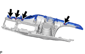
Install the No. 2 console box support with the 4 screws.
58861A
17.INSTALL NO. 1 CONSOLE BOX SUPPORT
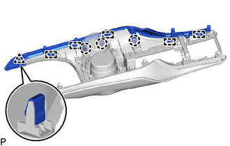
Engage the 5 guides, 3 claws and clip.

Install the No. 1 console box support with the 4 screws.
18.INSTALL CONNECTOR BRACKET (w/o Illumination)
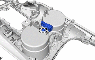
Engage the clamp to install the connector bracket.
81080K
19.INSTALL CONSOLE BOX ILLUMINATION LIGHT ASSEMBLY (w/ Illumination)