BRAKE SYSTEM (OTHER) BRAKE PEDAL(for Gasoline Model) ADJUSTMENT
PROCEDURE

 1.INSPECT AND ADJUST BRAKE PEDAL HEIGHT
Remove the front door scuff plate LH.
Remove the cowl side trim sub-assembly LH.
Remove the accelerator pedal pad.
Remove the accelerator pedal assembly.
Check the brake pedal height.
- HINT:
-
Inspect and adjust the brake pedal height with the floor carpet and front floor mat folded back.
Measure the shortest distance between the brake pedal pad surface and floor panel as shown in the illustration.
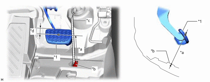
| *1 | Brake Pedal Pad | - | - |
| *a | Brake Pedal Height | *b | Measuring Plane of Floor Panel |
| *c | Ruler | *d | 36 mm (1.42 in.) |
- Brake Pedal Height from Floor Panel:
155.6 to 171.6 mm (6.13 to 6.76 in.)
- HINT:
-
If the brake pedal height is not as specified, inspect and adjust the push rod length according to the procedure below.
Adjust the push rod length.
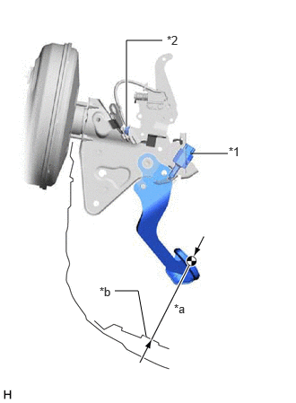
| *1 | Stop Light Switch Assembly |
| *2 | Lock Nut |
| *a | Brake Pedal Height |
| *b | Measuring Plane of Floor Panel |
Remove the stop light switch assembly.
Loosen the lock nut.
Adjust the brake pedal height by turning the push rod.
- Brake Pedal Height from Floor Panel:
155.6 to 171.6 mm (6.13 to 6.76 in.)
Tighten the lock nut.
- Torque:
- 26 N*m (265 kgf*cm, 19 ft.*lbf)
Install the stop light switch assembly.
Install the accelerator pedal assembly.
Install the accelerator pedal pad.
Install the cowl side trim sub-assembly LH.
Install the front door scuff plate LH.
2.INSPECT BRAKE PEDAL FREE PLAY
Stop the engine and firmly depress the brake pedal several times until no vacuum is left in the brake booster.
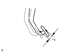
| *a | Brake Pedal Free Play |
Depress the brake pedal until a slight resistance is felt. Measure the distance as shown in the illustration.
- Brake Pedal Free Play:
1.0 to 6.0 mm (0.0394 to 0.236 in.)
- HINT:
- ·
If the brake pedal free play is not as specified, check the stop light switch clearance.
·If the brake pedal free play is as specified, proceed to the Inspect Brake Pedal Reserve Distance procedure.
3.INSPECT BRAKE PEDAL RESERVE DISTANCE
With the engine running, depress the brake pedal and measure the brake pedal reserve distance as shown in the illustration.

| *1 | Brake Pedal Pad | - | - |
| *a | Brake Pedal Reserve Distance | *b | Measuring Plane of Floor Panel |
| *c | Ruler | - | - |
- Brake Pedal Reserve Distance from Floor Panel at 300 N (31 kgf, 67.4 lbf):
129 mm (5.08 in.) or more