PARK ASSIST / MONITORING BLIND SPOT MONITOR SYSTEM Power Source Circuit
DESCRIPTION
This circuit provides power to operate the blind spot monitor sensor.
WIRING DIAGRAM
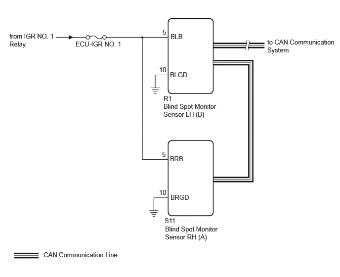
CAUTION / NOTICE / HINT
- NOTICE:
-
Inspect the fuses for circuits related to this system before performing the following procedure.
PROCEDURE
Disconnect the R1 blind spot monitor sensor LH (B) connector.
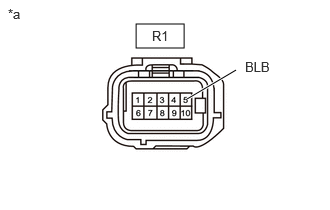
| *a | Front view of wire harness connector
(to Blind Spot Monitor Sensor LH (B)) |
Measure the voltage according to the value(s) in the table below.
- Standard Voltage:
Tester Connection Switch Condition Specified Condition Click Location & Routing(R1)Location & Routingewd_type=routing;type=c;code=R1
Click Connector(R1)Body>Luggage Room Wire>Blind Spot Monitor Sensor LHewd_type=component;type=c;code=R1;pinno=5
R1-5 (BLB) - Body ground Ignition switch ON 11 to 14 V R1-5 (BLB) - Body ground Ignition switch off Below 1 V
- Result:
Proceed to OK NG
OK
NG
Measure the resistance according to the value(s) in the table below.
- Standard Resistance:
Tester Connection Condition Specified Condition Click Location & Routing(R1)Location & Routingewd_type=routing;type=c;code=R1
Click Connector(R1)Body>Luggage Room Wire>Blind Spot Monitor Sensor LHewd_type=component;type=c;code=R1;pinno=10
R1-10 (BLGD) - Body ground Always Below 1 Ω
- Result:
Proceed to OK NG
OK
NG
Disconnect the S11 blind spot monitor sensor RH (A) connector.
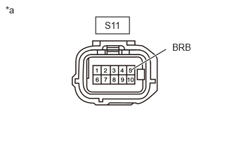
| *a | Front view of wire harness connector
(to Blind Spot Monitor Sensor RH (A)) |
Measure the voltage according to the value(s) in the table below.
- Standard Voltage:
Tester Connection Switch Condition Specified Condition Click Location & Routing(S11)Location & Routingewd_type=routing;type=c;code=S11
Click Connector(S11)Body>No. 2 Luggage Room Wire / No. 3 Luggage Room Wire>Blind Spot Monitor Sensor RHewd_type=component;type=c;code=S11;pinno=5
S11-5 (BRB) - Body ground Ignition switch ON 11 to 14 V S11-5 (BRB) - Body ground Ignition switch off Below 1 V
- Result:
Proceed to OK NG
OK
NG
Measure the resistance according to the value(s) in the table below.
- Standard Resistance:
Tester Connection Condition Specified Condition Click Location & Routing(S11)Location & Routingewd_type=routing;type=c;code=S11
Click Connector(S11)Body>No. 2 Luggage Room Wire / No. 3 Luggage Room Wire>Blind Spot Monitor Sensor RHewd_type=component;type=c;code=S11;pinno=10
S11-10 (BRGD) - Body ground Always Below 1 Ω
- Result:
Proceed to OK NG
OK
NG