MIRROR (EXT) OUTER REAR VIEW MIRROR DISASSEMBLY
CAUTION / NOTICE / HINT
- HINT:
- ·
Use the same procedure for the RH side and LH side.
·The following procedure is for the LH side.
PROCEDURE

 87961
1.REMOVE OUTER MIRROR
87961
1.REMOVE OUTER MIRROR
87945
2.REMOVE OUTER MIRROR COVER
3.REMOVE NO. 2 OUTER MIRROR COVER
w/ Panoramic View Monitor System:
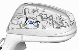
Disengage the clamp.
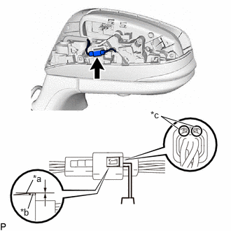
| *a | Claw |
| *b | Protrusion |
| *c | Insert Position |
Insert a 0.9 mm (0.0354 in.) spark plug gap gauge or similar tool into the connector as shown in the illustration.
- NOTICE:
- ·
Insert the spark plug gap gauge to the point that the claw becomes the same height as the protrusion of the connector housing. If the spark plug gap gauge is inserted too far, or if the claw is lifted directly using a screwdriver, the claw may be damaged.
·If the claw of the connector is damaged, replace the outer rear view mirror assembly.
Lift the claw and disconnect the connector.
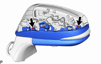
Remove the 2 screws.
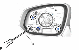
| *a | Protective Tape |
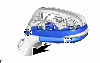
Using a screwdriver with its tip wrapped with protective tape, disengage the 3 claws.

|
Remove in this Direction |
Disengage the claw and guide as shown in the illustration.
w/ Foot Light:
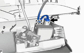
Disengage the clamp.
Disconnect the connector to remove the No. 2 outer mirror cover.
86790F
4.REMOVE SIDE TELEVISION CAMERA ASSEMBLY (w/ Panoramic View Monitor System)
81740
5.REMOVE SIDE TURN SIGNAL LIGHT ASSEMBLY