RM38N0EC _58 Vehicle Interior _111836 MIRROR (INT) _0499905 DIGITAL REAR-VIEW MIRROR SYSTEM D

MIRROR (INT)  DIGITAL REAR-VIEW MIRROR SYSTEM  OPERATION CHECK  


HINT:
·

It is only necessary to perform an inspection when there are dents or distortion in the back door panel sub-assembly as a result of an accident.

·

Inspections are not required when replacing parts or removing and reinstalling.


CAMERA IMAGE RANGE CONFIRMATION PROCEDURE


a.

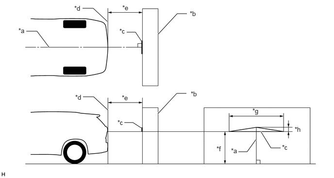
Set the vehicle in the position shown in the illustration and create a target on the wall.

NOTICE:
·

Perform this inspection on a level surface.

·

Remove all luggage from the vehicle before starting work.

·

Adjust the tire pressures to the specified pressure before starting work.


B572328C02
2.302,0.458 2,0.177 2,0.177 1.771,0.177 true 3.031,0.875 2.906,0.688 2.906,0.688 2.719,0.688 true 3.396,0.729 3.802,0.292 3.802,0.292 4.01,0.292 true 2.313,2.354 2.01,2.073 2.01,2.073 1.781,2.073 true 3.031,2.74 2.854,2.625 2.854,2.625 2.667,2.625 true 3.385,2.438 3.792,2 3.792,2 4,2 true 1.052,1.01 0.792,0.667 0.792,0.667 0.563,0.667 true 5.49,2.99 5.302,3.25 5.302,3.25 5.115,3.25 true 5.594,2.813 5.813,3.167 5.813,3.167 6.021,3.167 true 0.396,0.573 0.677,0.781 0.281,0.208 10 false *a 4.094,1.927 4.385,2.135 0.292,0.208 10 false *b 2.563,0.583 2.865,0.792 0.302,0.208 10 false *c 1.594,0.094 1.948,0.323 0.354,0.229 10 false *d 2.625,0.083 2.938,0.24 0.313,0.156 10 false *e 4.646,3.104 4.958,3.26 0.313,0.156 10 false *f 5.417,2.292 5.74,2.531 0.323,0.24 10 false *g 6.323,2.688 6.552,2.906 0.229,0.219 10 false *h 2.615,2.01 2.927,2.167 0.313,0.156 10 false *e 1.615,2 1.927,2.198 0.313,0.198 10 false *d 2.521,2.542 2.844,2.729 0.323,0.188 10 false *c 4.073,0.208 4.385,0.479 0.313,0.271 10 false *b 4.958,3.146 5.271,3.302 0.313,0.156 10 false *a 6.052,3.073 6.354,3.302 0.302,0.229 10 false *c
*a Vehicle Center *b Wall, etc.
*c Target *d Vehicle Rear End
*e 100 cm (3.28 ft.) *f 140.2 cm (4.60 ft.)
*g 55 cm (1.80 ft.) *h 3.6 cm (0.1417 in.)


b.
E431354C07
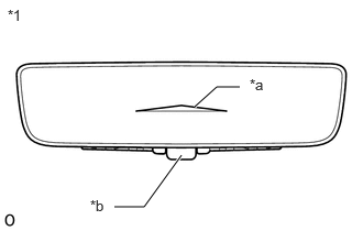
1.083,1.958 1.365,1.958 1.365,1.958 1.719,1.469 true 2.271,0.823 2.052,0.823 2.052,0.823 1.844,1.01 true 0.073,0.063 0.385,0.219 0.313,0.156 10 false *1 2.365,0.719 2.677,0.875 0.313,0.156 10 false *a 0.854,1.865 1.167,2.021 0.313,0.156 10 false *b
*1 Inner Rear View Mirror Assembly
*a Target
*b Mode Selection Lever


With the ignition switch ON, set the mode selection lever to the digital mirror mode side and check that the target is displayed as shown in the illustration.

HINT:
·

Make sure the system is set to the default settings (position, zoom, etc.).

·

If the target is as shown in the illustration, the system is working correctly.