LIGHTING (EXT) STOP LIGHT SWITCH ON-VEHICLE INSPECTION
PROCEDURE

 84340
1.INSPECT STOP LIGHT SWITCH ASSEMBLY
84340
1.INSPECT STOP LIGHT SWITCH ASSEMBLY
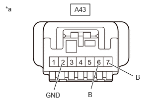
| *a | Front view of wire harness connector
(to Stop Light Switch Assembly) |
Disconnect the stop light switch assembly connector.
Measure the voltage and resistance on the wire harness side connector according to the value(s) in the table below.
- Standard Voltage:
Tester Connection Condition Specified Condition Click Location & Routing(A43)Location & Routingewd_type=routing;type=c;code=A43
Click Connector(A43)Instrument Panel>Engine Room Main Wire>Stop Light Switch Assemblyewd_type=component;type=c;code=A43;pinno=7,2,6
A43-7 (B) - A43-2 (GND) Always 11 to 14 V A43-6 (B) - A43-2 (GND) Ignition switch on (IG) 11 to 14 V
- Standard Resistance:
Tester Connection Condition Specified Condition Click Location & Routing(A43)Location & Routingewd_type=routing;type=c;code=A43
Click Connector(A43)Instrument Panel>Engine Room Main Wire>Stop Light Switch Assemblyewd_type=component;type=c;code=A43;pinno=2
A43-2 (GND) - Body ground Always Below 1 Ω
If the result is not as specified, repair or replace the wire harness or connector.
Reconnect the stop light switch assembly connector.
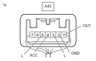
| *a | Component with harness connected
(Stop Light Switch Assembly) |
Measure the voltage according to the value(s) in the table below.
- Standard Voltage:
Tester Connection Condition Specified Condition Click Location & Routing(A43)Location & Routingewd_type=routing;type=c;code=A43
Click Connector(A43)Instrument Panel>Engine Room Main Wire>Stop Light Switch Assemblyewd_type=component;type=c;code=A43;pinno=1,2,3,4,5
A43-1 (OUT) - A43-2 (GND) Brake pedal not depressed 1.5 V or less A43-1 (OUT) - A43-2 (GND) Brake pedal depressed 11 to 14 V A43-3 (L) - A43-2 (GND) Brake pedal not depressed 1.5 V or less A43-3 (L) - A43-2 (GND) Brake pedal depressed 11 to 14 V A43-4 (ACC) - A43-2 (GND) Always 11 to 14 V A43-5 (L) - A43-2 (GND) Ignition switch on (IG), brake pedal not depressed 7.5 to 14 V A43-5 (L) - A43-2 (GND) Ignition switch on (IG), brake pedal depressed 0 to 1.5 V
If the result is not as specified, replace the stop light switch assembly.