HEATING / AIR CONDITIONING AIR CONDITIONING PRESSURE SENSOR ON-VEHICLE INSPECTION
PROCEDURE

 88719A
1.INSPECT AIR CONDITIONING PRESSURE SENSOR
88719A
1.INSPECT AIR CONDITIONING PRESSURE SENSOR
Check the wire harness.
Disconnect the A22 air conditioning pressure sensor connector.
Disconnect the E45 air conditioning amplifier assembly connector.
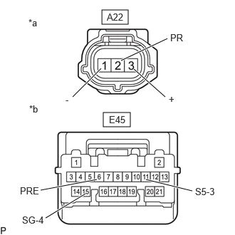
| *a | Front view of wire harness connector
(Air Conditioning Pressure Sensor) |
| *b | Front view of wire harness connector
(Air Conditioning Amplifier Assembly) |
Measure the resistance according to the value(s) in the table below.
- Standard Resistance:
Tester Connection Condition Specified Condition Click Location & Routing(A22,E45)Location & Routingewd_type=routing;type=c,c;code=A22,E45
Click Connector(A22)Engine Compartment>Engine Room Main Wire / Transmission Wire>Air Conditioning Pressure Sensorewd_type=component;type=c;code=A22;pinno=1,2,3
Click Connector(E45)Instrument Panel>Instrument Panel Wire / Radio Wiring Sub-Assy / Telephone Computer Wire>Air Conditioning Amplifier Assemblyewd_type=component;type=c;code=E45;pinno=15,6,11
A22-1 (-) - E45-15 (SG-4) Always Below 1 Ω A22-2 (PR) - E45-6 (PRE) Always Below 1 Ω A22-3 (+) - E45-11 (S5-3) Always Below 1 Ω A22-1 (-) or E45-15 (SG-4) - Other terminals and body ground Always 10 kΩ or higher A22-2 (PR) or E45-6 (PRE) - Other terminals and body ground Always 10 kΩ or higher A22-3 (+) or E45-11 (S5-3) - Other terminals and body ground Always 10 kΩ or higher
If the resistance is not as specified, repair or replace the wire harness.
Connect the E45 air conditioning amplifier assembly connector.
Turn the ignition switch to ON.
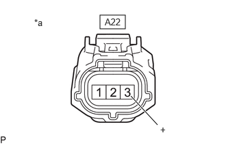
| *a | Front view of wire harness connector
(Air Conditioning Pressure Sensor) |
Measure the voltage according to the value(s) in the table below.
- Standard Voltage:
Tester Connection Condition Specified Condition Click Location & Routing(A22)Location & Routingewd_type=routing;type=c;code=A22
Click Connector(A22)Engine Compartment>Engine Room Main Wire / Transmission Wire>Air Conditioning Pressure Sensorewd_type=component;type=c;code=A22;pinno=3
A22-3 (+) - Body ground Ignition switch on (IG) 4.75 to 5.25 V
If the result is not as specified, repair or replace the wire harness or replace the air conditioning amplifier assembly.
Check the air conditioning pressure sensor.
Connect the A22 air conditioning pressure sensor connector.
Install a manifold gauge set.
Turn the A/C switch on.
Measure the voltage according to the value(s) in the table below.
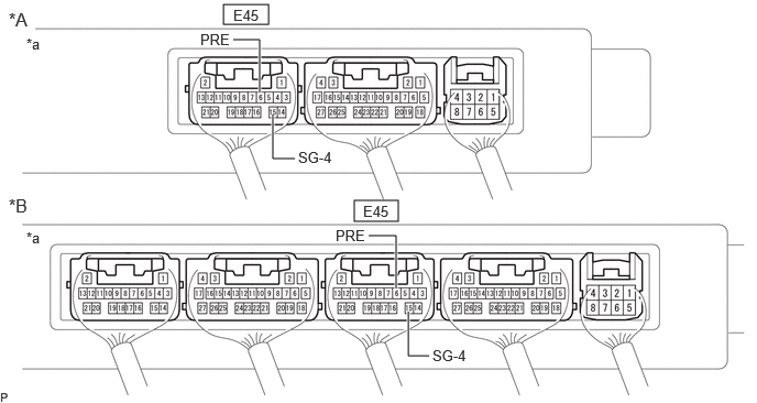
| *A | w/o Seat Heater System | *B | w/ Seat Heater System |
| *a | Component with harness connected
(Air Conditioning Amplifier Assembly) |
- | - |
- HINT:
-
Check from the rear of the connector while it is connected to the air conditioning amplifier assembly.
- Standard Voltage:
Tester Connection Condition Specified Condition *: While sensor voltage is 5 V.
Click Location & Routing(E45)Location & Routingewd_type=routing;type=c;code=E45
Click Connector(E45)Instrument Panel>Instrument Panel Wire / Radio Wiring Sub-Assy / Telephone Computer Wire>Air Conditioning Amplifier Assemblyewd_type=component;type=c;code=E45;pinno=6,15
E45-6 (PRE) - E45-15 (SG-4) Refrigerant pressure: Normal pressure (less than 3025 kPa (30.8 kgf/cm2, 439 psi) and more than 176 kPa (1.8 kgf/cm2, 26 psi)) 0.62 to 4.73 V*
If the voltage is not as specified, replace the air conditioning pressure sensor.