HEATING / AIR CONDITIONING FRONT AIR CONDITIONING UNIT REASSEMBLY
PROCEDURE

 88625
1.INSTALL NO. 1 COOLER THERMISTOR
88625
1.INSTALL NO. 1 COOLER THERMISTOR
88501
2.INSTALL NO. 1 COOLER EVAPORATOR SUB-ASSEMBLY
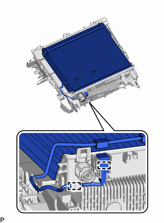
Install the No. 1 cooler evaporator sub-assembly with No. 1 cooler thermistor to the upper heater case.
Engage the 2 clamps.
Engage the 9 guides and 10 claws.
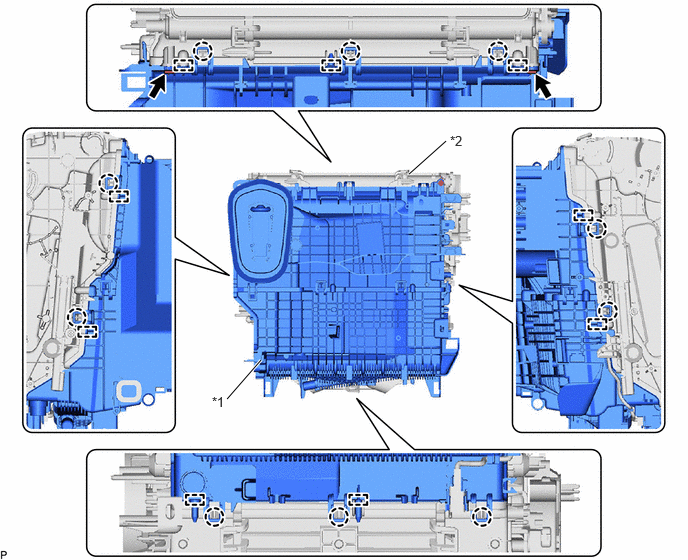
| *1 | Upper Heater Case | *2 | Lower Heater Case |
Install the upper heater case with No. 1 cooler evaporator sub-assembly to the lower heater case with the 2 screws.
88515
3.INSTALL COOLER EXPANSION VALVE
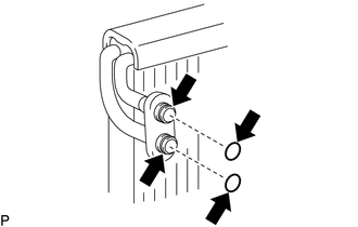
Sufficiently apply compressor oil to 2 new O-rings and the fitting surfaces of the No. 1 cooler evaporator sub-assembly.
- for HV Model:
Compressor Oil (ND-OIL 11 or equivalent)
- for Gasoline Model:
Compressor Oil (ND-OIL 8 or equivalent)
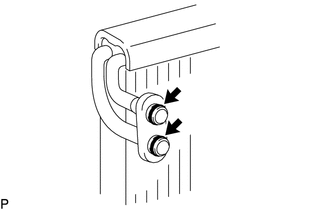
Install the 2 O-rings to the No. 1 cooler evaporator sub-assembly.
- NOTICE:
-
Keep the O-rings and O-ring fitting surfaces free of foreign matter.
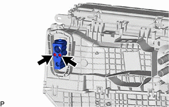
Using a 4 mm hexagon socket wrench, install the cooler expansion valve with the 2 hexagon bolts.
- Torque:
- 3.5 N*m (36 kgf*cm, 31 in.*lbf)
88899L
4.INSTALL COOLING UNIT PARTS
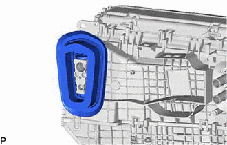
Install the cooling unit parts.
87107A
5.INSTALL HEATER RADIATOR UNIT SUB-ASSEMBLY

|
Install in this Direction |
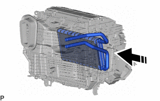
Install the heater radiator unit sub-assembly as shown in the illustration.
87124B
6.INSTALL HEATER CLAMP
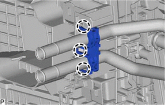
Engage the 3 claws to install the heater clamp.
88897M
7.INSTALL HEATER PIPE GROMMET
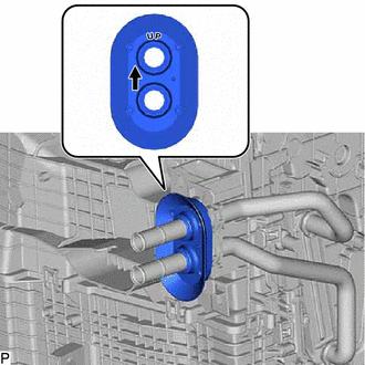
| *a | Reference Point |
Install the heater pipe grommet as shown in the illustration.
- NOTICE:
-
Install the heater pipe grommet with the arrow facing up.
88650N
8.INSTALL AIR CONDITIONING AMPLIFIER ASSEMBLY
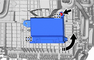
|
|
Install in this Direction |
Engage the 2 guides to temporarily install the air conditioning amplifier assembly as shown in the illustration.
Install the air conditioning amplifier assembly with the screw.
87114B
9.INSTALL HEATER COVER

|
|
Install in this Direction |
Install the heater cover as shown in the illustration.
Install the screw.
87050D
10.INSTALL NO. 2 AIR CONDITIONING RADIATOR DAMPER SERVO SUB-ASSEMBLY
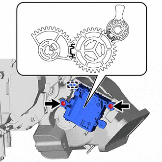
| *a | Reference Point |
Using the reference points, engage the guide to install the No. 2 air conditioning radiator damper servo sub-assembly with the 2 screws.
87050C
11.INSTALL NO. 1 AIR CONDITIONING RADIATOR DAMPER SERVO SUB-ASSEMBLY
Align each gear on the air conditioning radiator assembly as shown in the illustration, and then check that the gears of the No. 1 air conditioning radiator damper servo sub-assembly are aligned as shown in the illustration.
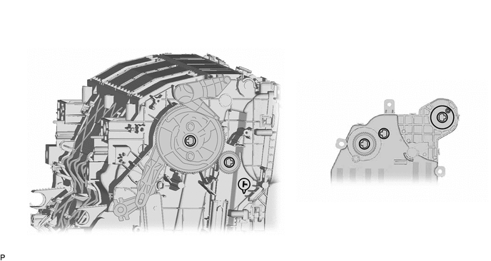
| *a | Reference Point | - | - |
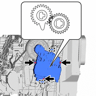
| *a | Reference Point |
Using the reference points, engage the 2 guides to install the No. 1 air conditioning radiator damper servo sub-assembly with the 3 screws.
82210K
12.INSTALL AIR CONDITIONING HARNESS ASSEMBLY
Engage each clamp.
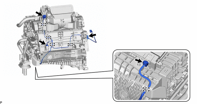
Connect each connector to install the air conditioning harness assembly.
88897P
13.INSTALL ASPIRATOR
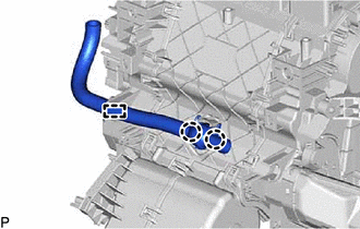
Engage the 2 claws and guide to install the aspirator.
87201B
14.INSTALL NO. 2 AIR DUCT SUB-ASSEMBLY
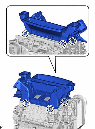
Engage the 6 claws to install the No. 2 air duct sub-assembly.
87130D
15.INSTALL BLOWER ASSEMBLY