RM38N0EC
_52
Drivetrain
_111806
K120 / K120F / K121 / K121F CVT
_0499744
COMBINATION SWITCH
G
K120 / K120F / K121 / K121F CVT COMBINATION SWITCH INSPECTION
PROCEDURE

 84970
1.INSPECT DRIVE MODE SELECT SWITCH (COMBINATION SWITCH ASSEMBLY)
84970
1.INSPECT DRIVE MODE SELECT SWITCH (COMBINATION SWITCH ASSEMBLY)
a.
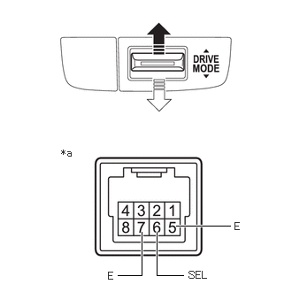
2.073,2.656 2.708,2.656
true
2.156,3.24 1.844,3.24
1.844,3.24 1.844,2.729
true
1.385,3.24 1.667,3.24
1.667,3.24 1.667,2.729
true
0.719,1.729 0.969,1.927
0.25,0.198
10
false
*a
2.76,2.594 2.948,2.813
0.188,0.219
10
false
E
2.219,3.167 2.583,3.375
0.365,0.208
10
false
SEL
1.271,3.177 1.469,3.375
0.198,0.198
10
false
E
| *a | Component without harness connected
(Drive Mode Select Switch (Combination Switch Assembly)) |

|
"A" Side |

|
"B" Side |
Measure the resistance according to the value(s) in the table below.
- Standard Resistance:
Tester Connection Condition Specified Condition 6 (SEL) - 5 (E) Pushed and held at "A" side Below 50 Ω Released (neutral position) 10 kΩ or higher 7 (E) - 5 (E) Pushed and held at "B" side Below 50 Ω Released (neutral position) 10 kΩ or higher
If the result is not as specified, replace the drive mode select switch (combination switch assembly).
b.
0.708,0.292 0.979,0.292
0.979,0.292 1.396,1.125
true
2.698,0.292 2.448,0.292
2.448,0.292 2.031,1.125
true
0.042,0.042 0.354,0.198
0.313,0.156
10
false
*a
0.365,0.208 0.979,0.406
0.615,0.198
10
false
ILL+
2.792,0.219 3.406,0.417
0.615,0.198
10
false
ILL-
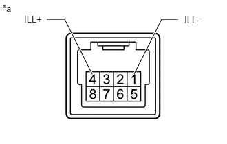
| *a | Component without harness connected
(Drive Mode Select Switch (Combination Switch Assembly)) |
Apply battery voltage between the terminals of the switch and check the illumination condition of the drive mode select switch (combination switch assembly).
- Standard:
Measurement Condition Specified Condition Battery positive (+) → 4 (ILL+)
Battery negative (-) → 1 (ILL-)Illuminates
If the result is not as specified, replace the drive mode select switch (combination switch assembly).